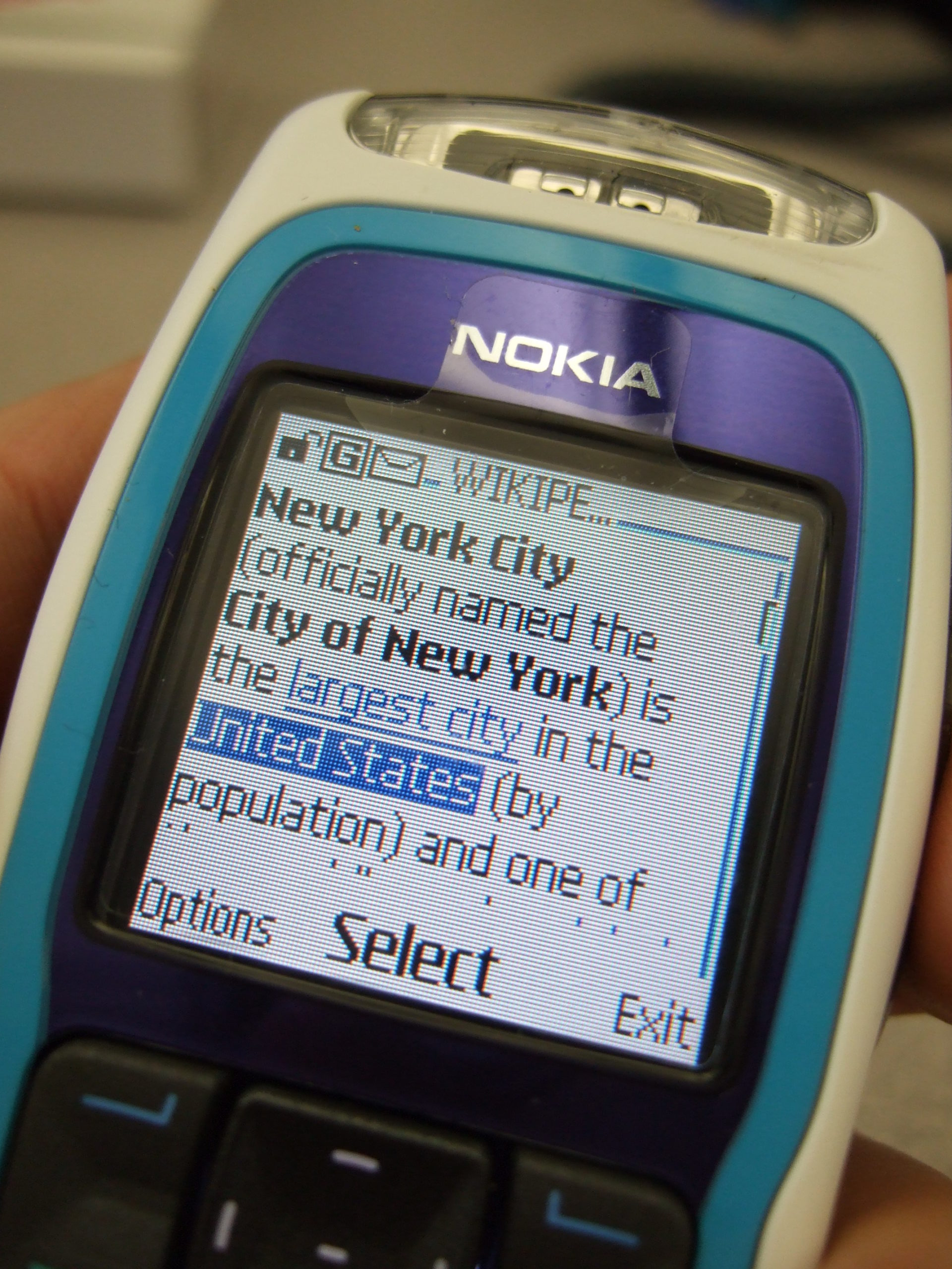
So far we’ve focused on building a plain “2G” (voice and SMS only) network, which was all consumers expected twenty years ago.
As the number of users accessing the internet through DSL, Dial Up & ISDN grew, the idea of getting this data “on the go” became more appealing. TCP/IP was becoming the dominant standard for networking, the first 802.11 WiFi spec had recently been published and demand for mobile data was growing.
There’s a catch however – TCP/IP was never designed to be mobile.
An IP address exists in a single location.
(Disclaimer: While you can “move” a subnet by advertising itself out in a different location via BGP peering relationships with other operators, it’s cumbersome, can only be done per /24 or larger, and most importantly it’s painfully slow. IPv6 has MIPv6 which attempts to fix some of these points, but that’s outside of this scope.)
GPRS addressed the mobility issue by having a single fixed point the IP Address is assigned to (the Gateway GPRS Support Node), which encapsulates IP traffic to/from a mobile user into GTP Packet (GPRS Tunnelling Protocol), like GRE or any of the other common routing encapsulation protocols, allowing the traffic to be rerouted to different destinations as the users move from being served by one BTS to another BTS.
I’ve written about GTP here if you’d like to learn more.
So now we’ve got a method of encapsulating our data we’ve got to work out how to get that data out over the air.
BTS Time Slots
Way back when we were first setting up our BSC and adding our BTS(s) you will have configured timeslots for each BTS configured on your BSC.
Chances are if you’ve been following along with this tutorial, that you configured the first time slot (timeslot 0) as a CCCH+SDCCH4, meaning Common Control Channel and 4 standalone dedicated control channels, and all the subsequent timeslots (timeslot 1 – 7) as Traffic Channels (full rate) – TCH/F.
This works well if we’re only carrying voice, but to carry data we need timeslots to put the data traffic on.
For this we’ll re assign a timeslot we were using on our BSC as a voice traffic channel (TCH/F) as a PDCH – a Packet Data Channel.
This means that on the BSC your timeslot config will look something like this:
   timeslot 6
    phys_chan_config PDCH
    hopping enabled 0
   timeslot 7
    phys_chan_config PDCH
    hopping enabled 0
In the above example I’ve assigned two timeslots for Packet Data Channels,
The more timeslots you allocate for data, the more bandwidth available, but the fewer voice resources available.
(Most GSM networks today have few data timeslots as more recent RATs like 3G/4G are taking the data traffic, and GSM is used primarily for voice and low bandwidth M2M communications)
GPRS and EDGE
GPRS comes in two flavors, GPRS and EDGE.
GPRS (General Packet Radio Services) was the first of the two, standardised in R97, and allowed users to reach a downlink speeds of up to 171Kbps using GMSK on the air interface to encode the data.
Users quickly expected more speed, so EDGE (Enhanced Data rates for Global Evolution) was standardised, from a core perspective it was the same, but from a BTS / Air interface perspective it relied on 8PSK instead of GMSK allowed users to reach a blistering 384Kbps on the downlink.
These speeds are the theoretical maximums.
As the difference between GPRS and EDGE is encoding on the air interface, from a core perspective it’s treated the same way, however as our BTS gets all it’s brains from the BSC, we’ll need to specify if the BTS should use EDGE or GPRS it in the BSC’s BTS config.
BSC Config
On the BSC for each BTS we want to enable for packet data, we’ll need to define the parameters.
There’s two other values we’ll introduce when setting this up,
The first is NSEI – the Network Service Entity Identifier, which is the identifier of the BTS’s Packet Control Unit, like the cell identity.
The second value we’ll touch on is the BVCI – the BSSGP Virtual Connections Identifier, which is used for addressing between the BTS PCU and the SGSN.
bts 0
  gprs mode egprs
  gprs 11bit_rach_support_for_egprs 0
  gprs routing area 0
  gprs network-control-order nc0
  gprs cell bvci 2
  gprs cell timer blocking-timer 3
  gprs cell timer blocking-retries 3
  gprs cell timer unblocking-retries 3
  gprs cell timer reset-timer 3
  gprs cell timer reset-retries 3
  gprs cell timer suspend-timer 10
  gprs cell timer suspend-retries 3
  gprs cell timer resume-timer 10
  gprs cell timer resume-retries 3
  gprs cell timer capability-update-timer 10
  gprs cell timer capability-update-retries 3
  gprs nsei 101
  gprs ns timer tns-block 3
  gprs ns timer tns-block-retries 3
  gprs ns timer tns-reset 3
  gprs ns timer tns-reset-retries 3
  gprs ns timer tns-test 30
  gprs ns timer tns-alive 3
  gprs ns timer tns-alive-retries 10
  gprs nsvc 0 nsvci 101
  gprs nsvc 0 local udp port 23001
  gprs nsvc 0 remote udp port 23000
  gprs nsvc 0 remote ip 10.0.1.201
The OsmoBSC docs cover each of these values, they’re essentially defaults.
In the next post we’ll cover the GGSN and the SGSN and then getting a device on “the net”.
