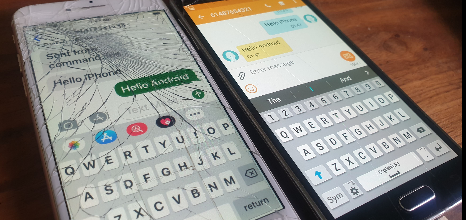
One nifty feature of this interface is that you can send SMS using the MSC to switch the SMS traffic and the LTE/EUTRAN to transfer the messaging.
This means you don’t need Circuit Switched Fallback to send or receive SMS on LTE.
I assume this functionality was added to avoid the signalling load of constantly changing RAN technologies each time a subscriber sent or received an SMS, but I couldn’t find much about it’s history.
In order to get this to work you’ll essentially need the exact same setup I outlined in my CSFB example (Osmo-MSC, Osmo-STP, Osmo-HLR populated with the IMSI and MSISDN values you want to use for SMS), although you won’t actually need a GERAN / GSM radio network.
Once that’s in place you can just send SMS between subscribers,
Plus from the VTY terminal of OsmoMSC you can send SMS too:
I’ve talked about how LTE’s EUTRAN / EPC has no knowledge about voice calls or SMS and instead relies on IMS/VoLTE for these services.
Circuit Switched Fallback allows UEs to use a 2G or 3G network (Circuit Switched network) if their device isn’t connected to the IMS network to make calls as the 2G/3G network can handle the voice call or SMS routing via the Mobile Switching Center in the 2G/3G network.
However for incoming calls destined to the UE (Mobile Terminated) the MSC needs a way to keep track of which MME is serving the UE so it can get a message to the MME and the MME can relay it to the UE, to tell it to drop to a 2G or 3G network (Circuit Switched network).
The signalling between the MME (In the LTE EPC) and the MSC (In the GSM/UTRAN core) is done over the SGs interface.
While the SGs interface is primarily for managing user location state across multiple RAN types, it’s got a useful function for sending SMS over SGi, allowing users on an LTE RAN to send SMS via the MSC of the 2G/3G network (GSM/UTRAN core).
How it Works:
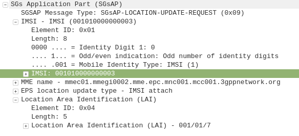
When a UE connects to the LTE RAN (EUTRAN) the MME signals the GSM/UMTS MSC with an SGsAP-LOCATION-UPDATE-REQUEST,
This request includes the IMSI of the subscriber that just attached and the FQDN of the MME serving that UE.
The MSC now knows that IMSI 001010000000003 is currently on LTE RAN served by MME mmec01.mmegi0002.mme.epc.mnc001.mcc001.3gppnetwork.org,
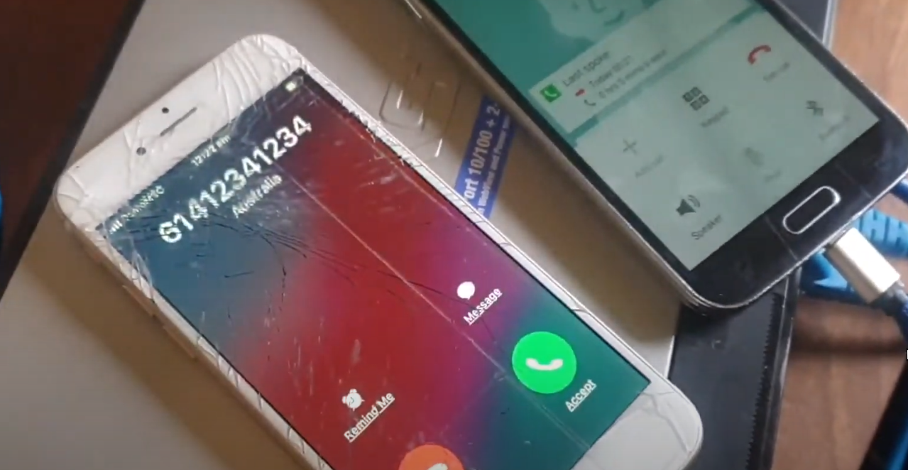
If a call or SMS comes into the MSC destined for the MSISDN of that IMSI, the MSC can page the UE on the LTE RAN to tell it to do an inter-RAN handover to GSM/UMTS.
Setting it Up
In order to get this working you’ll need OsmoMSC in place, your subscribers to exist on OsmoHLR and the LTE HSS – For example Open5GS-HSS.
Once you’ve done that the additional config on OsmoMSC is fairly simple, we just define a new SGs interface to listen on:
OsmoMSC Config:
sgs
  local-port 29118
  local-ip 0.0.0.0
  vlr-name vlr.msc001.mnc001.mcc001.3gppnetwork.org
end
On the Open5GS side we’ve got to include the SGs info the MME config. Keep in mind the Tracking Area Code (TAC) in LTE must exist as the Location Area code (LAC) in GSM, here’s an extract of the MME section of YAML config in the Open5GS MME config:
The EUTRAN will need to advertise the presence of it’s GERAN neighbours and vise-versa so the UE/terminals know what ARFCN to move to so they don’t need to scan for the presence of other RATs when performing the handover.
Setting this up will depend on your eNB / BSC and goes beyond the scope of this post.
I’ll cover setting up neighbours in a later post as it’s a big topic.
If you don’t have neighbours configured, the handover will still work but will be much slower as the UE will have to scan to find the serving cell it’s reselecting to.
So we’ve got a functional network, but let’s dive deeper into what we can do to connect it with other networks and how things work in “the real world”.
Media Handling – OsmoMGW
The Audio/Voice (media stream) data on a call between subscribers does not go directly between the subscribers and instead needs to be proxed relayed. The reason for this is because there’s no direct link from one BTS to another BTS (even if they are served by the same BSC) and as our subscribers can move from cell to cell while on a call – which may mean moving from one BSC to another depending on where they’re heading – we need to have a single point for the audio to remain.
To handle this a Media Gateway is used, a single point for call audio to be “anchored” – meaning regardless of which BTS/BSC is serving the subscribers on either end of the call, the media will be sent by both parties to a single destination (The Media Gateway), and that destination will send the audio to the other party.
The Media gateway relays / proxies the Media Stream – the RTP packets containing the call audio. OsmoMSC provides the SDP payload containing the codecs and RTP details for the session via MGCP (Media Gateway Control Protocol) to the OsmoMGW which relays the audio.
In terms of running osmo-mgw we installed it earlier,
The only parameter you really need to change is the rtp bind-ip,
On the MGW you can also limit and restrict the codecs supported and also allow or disallow transcoding.
MNCC-SAP & Call Routing
In it’s default mode, the OsmoMSC will look at the destination a call is being sent to, and if the destination is a subscriber on the network (in it’s VLR), will route the call to that subscriber
This on-net only mode is great but it puts our network on an island – cut off from the outside world.
Calls between MSCs, to the PSTN and users everywhere else are not possible in this scenario.
3GPP defined “MNCC-SAP” (Mobile Network Call Control – Service Access Point) a protocol for handling calls to/from destinations outside of the local MSC.
When in MNCC-SAP mode all calls (even on-net calls between subscribers on the same MSC) are routed to the external MNCC-SAP, and left up to it to determine how to route the call.
Configuring Osmo-MSC to talk MNCC
As we just covered by default Osmo-MSC only switches calls internally between subscribers, so we’ll need to turn off this behaviour and isntead reconfigure it to talk MNCC-SAP.
To do this we’ll telnet / VTY into Osmo-MSC;
root@gsm-bts:/etc/osmocom# telnet localhost 4254
Welcome to the OsmoMSC VTY interface
OsmoMSC - Osmocom Circuit-Switched Core Network implementation
OsmoMSC> enable
OsmoMSC# configure terminal
OsmoMSC(config)# msc
OsmoMSC(config-msc)# mncc external /tmp/msc_mncc
OsmoMSC(config-msc)# end
OsmoMSC# cop run st
Configuration saved to /etc/osmocom/osmo-msc.cfg
After making this change we have to restart OsmoMSC;
systemctl restart osmo-msc
Now OsmoMSC will not switch calls locally, but instead when a mobile originated call comes to the MSC, it will signal to the external MNCC via the file sock at /tmp/msc_mncc,
MNCC-SAP sounds great but platform X only speaks SIP
Enter the Osmo-SIP-Connector, which takes the MNCC-SAP messages and converts them to SIP.
From here you can tie the call control functions of the MNC into any SIP software such as Kamailio, FreeSwitch, Asterisk, etc, to handle call routing, number translation, application services like voicemail and conferencing, etc, etc.
On my to-do list is to make a call between one subscriber on GSM and one on VoLTE, I’ll cover that in a subsequent post.
So anywho, let’s get Osmo-SIP-Connector setup, I’m running it on the same box as the MSC on 10.0.1.201, My softphone client is running on 10.0.1.252
root@gsm-bts:/etc/osmocom# apt-get install osmo-sip-connector
root@gsm-bts:/etc/osmocom# telnet localhost 4256
Welcome to the OsmoSIPcon VTY interface
OsmoSIPcon> enable
OsmoSIPcon# configure t
OsmoSIPcon(config)# mncc
OsmoSIPcon(config-mncc)# socket-path /tmp/msc_mncc
OsmoSIPcon(config-mncc)# exit
OsmoSIPcon(config)# sip
OsmoSIPcon(config-sip)# local 10.0.1.201 5060
OsmoSIPcon(config-sip)# remote 10.0.1.252 5060
OsmoSIPcon(config-sip)# end
OsmoSIPcon# cop run st
Configuration saved to /etc/osmocom/osmo-sip-connector.cfg
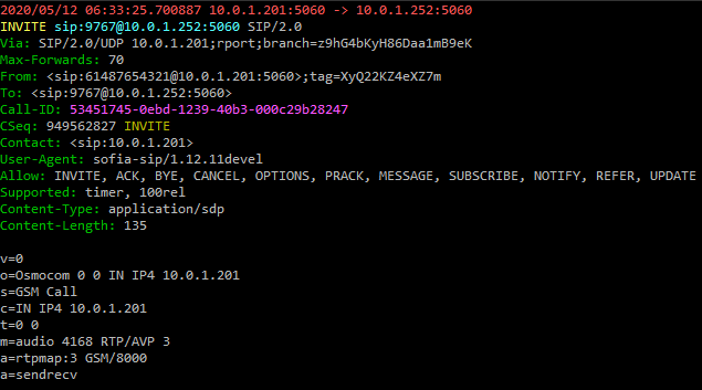
Now any Mobile Originated calls will result in a SIP INVITE being sent to 10.0.1.252 port 5060 (using UDP).
Any SIP INVITES where the request URI is a valid MSISDN @ 10.0.1.201 from 10.0.1.252 will be routed to the correct subscriber for that MSISDN.
A small note – The GSM codec is (unsurprisingly) used as the codec for GSM calls by default.
Some handsets support different codecs, but many off-the-shelf IP phones don’t include GSM support, so you may find you’re required to transcode between codecs if there is no support for the other codecs.
So now we’re able to define our call routing logic in something that speaks SIP and connect calls between multiple MSCs, VoLTE / IMS networks and fixed networks, all based on what we do with the SIP.
Local Call, Local Switch
If two subscribers on the same BSC call each other, the RTP / call audio will route to the MGW where it’s anchored.
This makes sense from a mobility standpoint, but adds load to the MGW and relies on a quality A interface connection, which may be an issue depending on what backhaul options you have.
Local Call, Local Switch is a 3GPP spec to allow the RTP / call audio to act as the RTP proxy instead of the MGW.
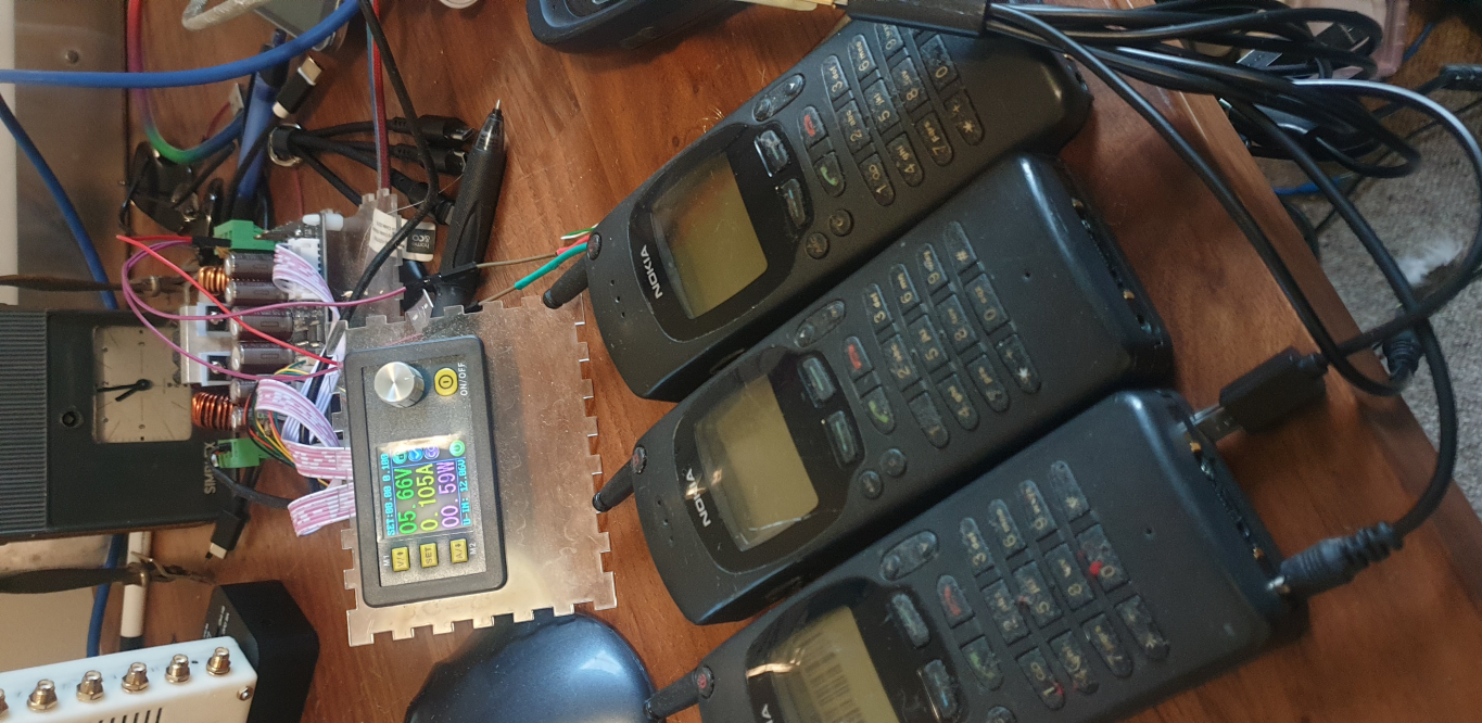
So now we’ve covered the basics of what’s involved let’s get some traffic on our network.
For starters we’ll need to start each of our network elements and bring up whichever BTS hardware we’re using.
In order for our calls to have audio, we’ll need to set a parameter on the Media Gateway. We’ll cover the Media Gateway in more detail down the line, but there’s one value in the MGW we’ll need to set in order to have calls working, and that’s the rtp bind-ip value. You can either set it in the config file or via VTY/Telnet on port 4243.
We’ve talked about using systemctl to start all the services, but there’s a script in the /etc/osmocom directory called osmocom-all.sh which starts all the network elements for us.
Once you’ve got all the services started I’d suggest hopping onto the OsmoBSC and enabling all the logging you can, then connecting / starting your BTS.
You should see the Abis over IP connection & OML link come up as the BTS connects to the BSC.
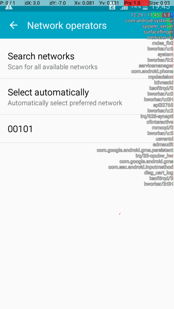
And then, hold your breath, power up a phone and search for networks.
All going well you’ll see OsmoMSC in the network search, select it and you should see log data flying by as the phone (“terminal”) connects to the network.
Assuming you configured the IMSI of the SIM on the HLR you should be connected to the network and showing bars on the phone.
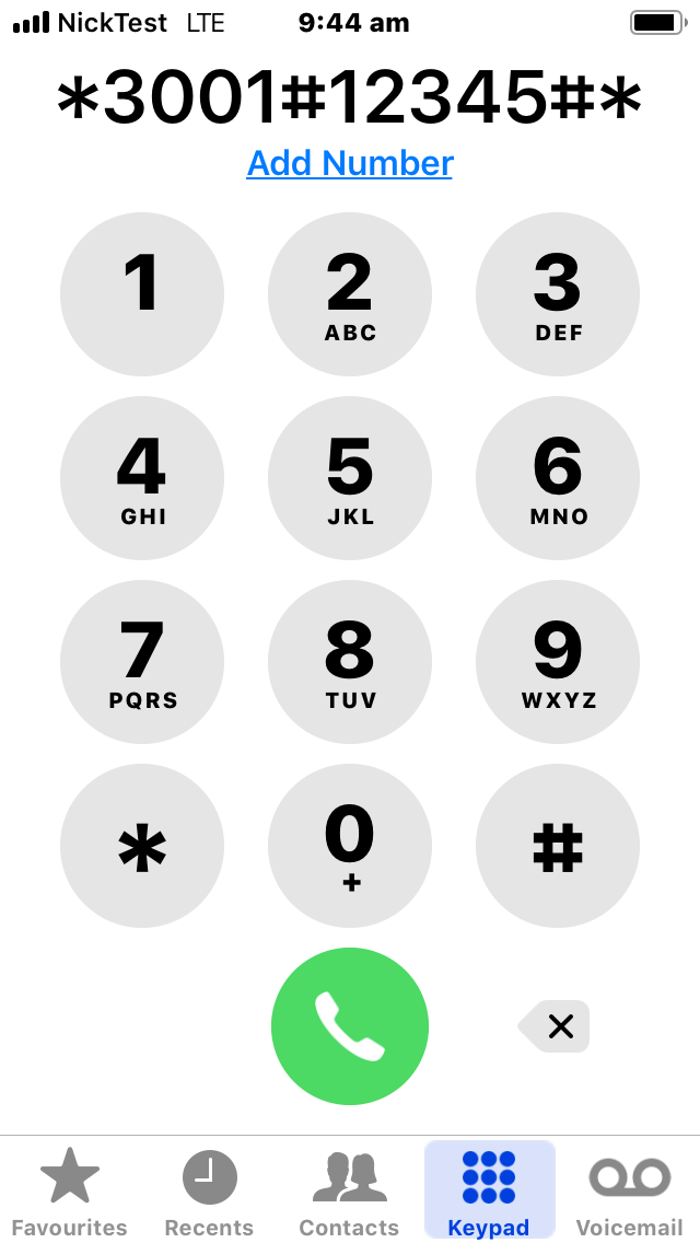
You can check your phone number (MSISDN) by dialling the USSD code *#100#
But it’s not a network with just one phone connected, connect a second phone, check it’s phone number the same way and call from one to the other.
SMS should also just work.
And there you have it, a functional GSM network!
But this isn’t the end for us, it’s really just the beginning.
There’s still so much more to learn and work on – Over the next few weeks / months we’ll add packet data to the network with GPRS or EDGE, connect into external call routing and SMS routing interfaces, use Circuit Switched Fallback to provide voice service to users on LTE networks and roam between them.
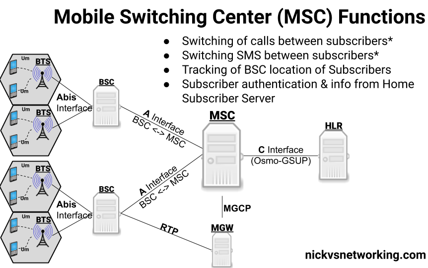
We’re nearing the end of our “setup” story – So far we’ve covered the access network (BTS & BSC) and our subscriber database (The HLR) so now let’s talk about one of the key “Core” elements of the network – the Mobile Switching Center (MSC).
The MSC’s name kind of says it all, it’s a switching center for mobiles.
The MSC handles switching of voice calls and SMS/text messages between local & remote subscribers and networks.
Switching Function
Because GSM was designed to be voice centric (Keep in mind the first GSM network went live in 1991) the MSC’s primary function is switching phone calls between subscribers.* For this the MSC has to keep track of which subscribers it’s currently serving, their capabilities and how to reach them -which BSC they’re being served by and therefore which BTS they’re being served by.
The OsmoMSC also features a minimalistic SMSC (Short Message Service Server) for routing SMS traffic between subscribers on the network. This basic SMSC acts in a store-and-forward fashion. Production networks would typically use an external SMSC for handling SMS, OsmoMSC has the SMSC functionality built in by default, but the interfaces are there if you wanted to use an external SMSC.
Any calls/texts to subscribers/destinations outside the MSC (for example a call to a mobile subscribers on a different carrier or on the PSTN) are typically routed to another MSC known as the Gateway MSC. The GMSC handles the interconnection with other networks. We’ll touch upon this later with the SIP connector, but for now we’ll focus just on on-net calls between subscribers.
It’s worth noting that the MSC does not sit in the media stream, it just sets up and tears down the calls, we’ll cover more on the nitty-gritty of calling in GSM soon.
Visitor Location Register Function
The MSC also acts as the interface to the HLR for AAA, as we covered in our last post, the HLR provides the authentication role and also provides the subscriber data to the MSC. Subscriber data is copied from the HLR to the internal HLR cache on the MSC known as the Visitor Location Register (VLR) after a subscriber attaches.
Authentication, Ciphering and EIR Queries
In the last post we talked about the role of the HLR in terms of Authentication on the network, the authentication vectors but the policies that enforce this are set on the MSC.
The MSC queries the admission control info from the HLR, but it’s the MSC that’s responsible for enforcing these rules.
Core Network Identity
The MCC (Mobile Country Code) and MNC (Mobile Network Code) of the network (Together the MCC + MNC are referred to as the PLMN ID), along with the network name, are configured on the MSC.
While this may seem like a rather small detail, the PLMN ID is analogous to the SSID of a WiFi network – it’s what identifies your network out of all the others on the air, and the network name shows up on your phone when you’re connected showing your network name.
Setup & Connections
The BSC we setup earlier communicates with the MSC via SS7 Point Codes. We’ll go into how point codes route requests in a later post, but so long as you’re running Osmo-BSC, Osmo-MGW, Omso-MSC and Osmo-HLR on the same machine you won’t need to link them to each other like we had to do with adding our BTS to the BSC.
Instead we’ll just need to start everything required:
The GSUP connection between the MSC and the HLR will be established at startup, but BSCs will only establish a connection to the MSC when they need something from the MSC.
Once we’ve got everything started we can Telnet into the MSC to confirm it’s running and check it’s status:
root@gsm # telnet localhost 4254
Assuming you can connect that’s another network element online. – We’ll leave the default the Point Codes in place so the BSC will be able to connect to the MSC, but keep in mind that the BSC will only establish a connection when it needs something from the MSC.
Follow Up
There’s a few topics we skipped over in this topic, stuff like SS7/SIGTRAN, how real world GSM calls route using MNCC-SAP, the Media Gateway and anchoring media streams and what an SMSC does.
I’ll do posts covering each of these topics in more depth.
The Home Location Register serves the AAA functions in a GSM / UMTS (2G/3G) network as well as locating which Mobile Switching Center (MSC) a subscriber is being served by.
One obvious need is to authenticate our subscribers so the network can verify their identity,
The IMSI (International Mobile Subscriber Identity) is used to identifier the user from all the other mobile subscribers worldwide. The IMSI is exposed to the user, but transmitting the IMSI in the clear is typically something that’s avoided where possible on the air interface.
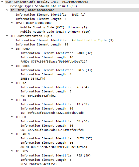
GSM uses a single shared secret between the SIM and the network (the K key) for authentication. This shared secret is not exposed to the user and is never transmitted over the air.
When a user wants to authenticate, the HSS network takes a Random key (RAND) and mixes it with the secret key (K) to generate a Signed Response called SRES. The network sends the RAND key to the subscriber, and their SIM takes the secret key (K) and mixes it with the RAND value from the network, before sending their signed response (SRES) back to the network. If the SRES sent by the subscriber matches the SRES generated by the HSS, then the user is authenticated. The set of keys used for one authentication session is referred to as an Authentication Vector or Authentication Tuple.
In Osmocom the generation of Authentication Tuples is requested in the GSUP “SendAuthInfo” request, and responded to by the “SendAuthInfoResponse” sent to the HLR by the MSC.
Side note about GSM Security
In a GSM setting the network only authenticates the subscribers, the subscribers don’t authenticate the network. In practice, this means there’s no way to verify in GSM if the network you’re connected to is the network it’s claiming to be.
Due to this shortfall and the cryptographic weakness in A5/x algorithm, 3GPP specified the AKA algorithm for mutual network authentication in 3G/UMTS networks.
Technically the generation of Authentication Vectors is handled by an Authentication Center (AuC) however OsomoHLR has an internal AuC that handles this internally.
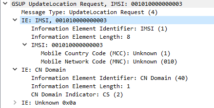
Location Tracking
After a user has authenticated, the MSC sends an UpdateLocationRequest via GSUP to the HLR to let it know the current location of the subscriber is served by that MSC.
The Update Location Request is sent at the start of the session, periodic Update Location Requests can be sent based on the timers configured, and a Cancel Location Request can be sent when the subscriber disconnects from the MSC.
Subscriber Data Information
When the Update Location Request has been sent by the MSC, the HLR sends the MSC the subscriber’s info, and the MSC copies it to it’s own internal HLR called a Visitor Location Register (VLR). The VLR means the MSC doesn’t need to keep querying user data from the HLR.
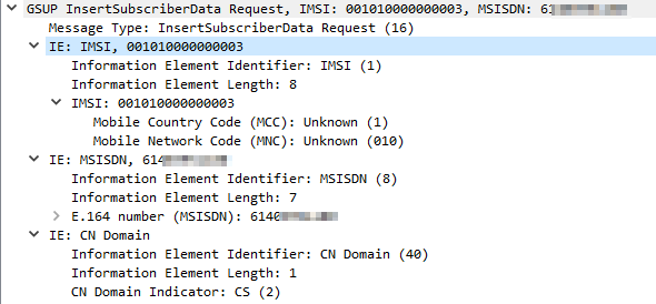
This is again requseted by the MSC to the HLR via a GSUP request InsertSubscriberData Request which contains:
Subscriber’s IMSI
Subscriber’s MSISDN (Phone number)
Allowed Domains (CS/PS)
Note: In production GSM networks TCAP/MAP is used for communication between the HLR and the MSC. Osmocom uses GSUP for carrying this data instead.
Equipment Identity Register
Because mobiles are expensive they’ve historically been a target for theft.
To try and mitigate this GSMA encourages carriers to implement an Equipment Identity Register (EIR).
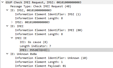
The EIR is essentially a database containing IMEIs (The Identifiers of Mobiles / Terminals) and permitting / denying access to the network based on the IMEI.
The idea being if a mobile device / terminal is stolen, it’s IMEI is blacklisted in the EIR and regardless of what SIM is put into it, it’s not permitted to access the network.
When a device connects to the network if configured the MSC will query the EIR (On the HLR in our case) with a Check IMEI Request, and will get a Check IMEI Result either permitting or denying access to the network.
Unfortunately, there is no global stolen IMEI database, meaning if a device is stolen and blocked on MNO X’s network, it may still work on MNO Y’s network if they don’t share stolen IMEI data.
Starting & Configuring OsmoHLR
We actually installed OmsoHLR in the post on Base Station Controllers, so we’ll just need to start the daemon / service:
systemctl start osmo-hlr
I’m going to enable the EIR functionality of the HSS by changing the config of the HLR, this is optional but it’s useful to use the EIR functionality.
Like with our other network elements we’ll use Tenet to interactively configure this one,
But before we go adding subscribers, let’s talk about SIMs.
Okay, I’ve written a lot about SIMs before, but there’s still more to talk about!
There’s really only one peice of information from your SIM we require to add the subscriber to the HLR, and that’s the IMSI – The unique identifier of the subscriber on the SIM. You can typically view the IMSI from your mobile device / terminal.
So I’ve created a subscriber with IMSI 001010000000004 in the HSS and assigned an MSISDN (phone number).
Optionally, if you’re using SIM cards you can program you can set the Ki / K key for authentication using the update aud2g function, if not you can skip that step.
And with that we’ve added our first subscriber, lather rinse repeat with any additional subscribers / SIMs you want to provision.
By default subscribers created using this method have access to both Circuit Switched (Voice and SMS) and Packet Switched (Data) networks. (We haven’t configured Packet Switched services yet)
If you’d like to restrict access to one, both or none of the above options, you can do that by using the subscriber update command to set the services available to those subscribers.
OsmoHLR# subscriber id 3 update network-access-mode cs+ps
OsmoHLR# subscriber id 3 update network-access-mode cs
OsmoHLR# subscriber id 3 update network-access-mode ps
OsmoHLR# subscriber id 3 update network-access-mode none
Creating Subscribers Programmatically
In reality if you’re trying to operate a network it’s not feasible to manually add each subscriber as needed.
If you’re buying SIMs in bulk preconfigured you’ll get sent a file containing the IMSI and Crypto values of each card, and you’d ingest that into your HLR.
We’ve used the Osmocom VTY / Telnet interface in quite a few posts now (hopefully you’re getting comfortable with it) but there’s another interface most Osmocom software has – the Osmocom Control Interface – aimed at providing a uniform way to interface external scripts / programs with Osmocom.
For most scenarios you would pre-provision each SIM in the HLR, if the SIM’s IMSI isn’t in the HLR then it’s access is rejected. However there are some scenarios where you may want to allow anyone to access the network, in this scenario Osmo-HLR features a “Create Subscribers on Demand” function.
This may be useful if you’re setting up a network where you don’t control the SIMs for example.
Let’s say we want to automatically create users with access to voice & data services and assign a 10 digit MSISDN for that subscriber, we can do that with:
Then if you wish to grant access to these users you can use the subscriber update network-access-mode method we talked about earlier to allow services for that user.
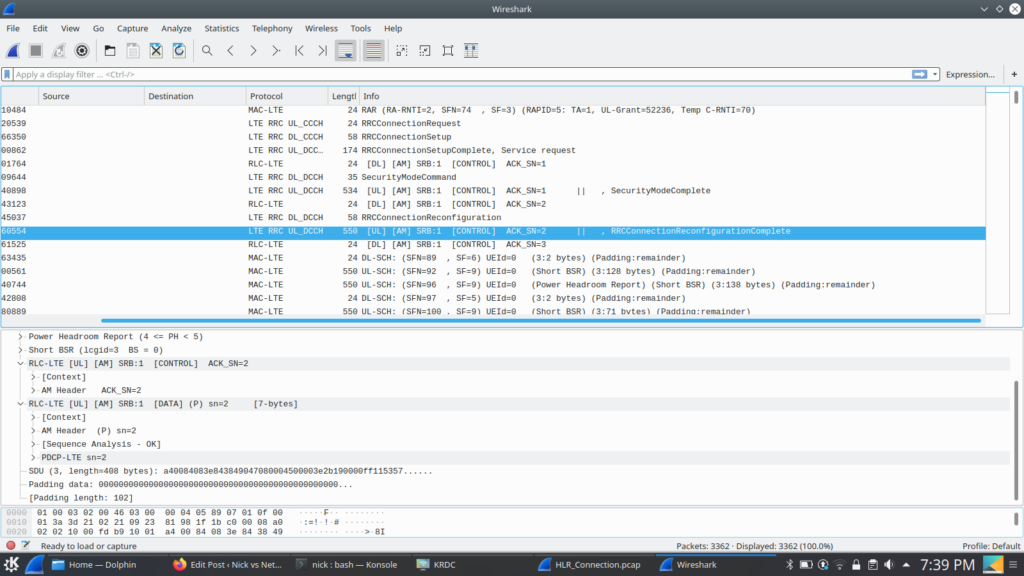
Packet Capture
To give some context I’ve attached a packet capture of the connection from the MSC to the HLR for some attach procedures on my lab network.
We’ll edit the oml remote-ip to the IP of the server running your BSC, if you’re running on on the same machine you can leave it as localhost (127.0.0.1).
Next up we’ll set the Unit-ID of the BTS, this identifies the BTS inside the BSC,
I’ll set it to unit-id 1234 by changing ipa unit-id 1234 0
Finally we’ll change the logging config to show everything by changing it to:
log stderr
 logging filter all 1
!
Next up we’ll configure the BTS on the BSC
BSC Provisioning
This is essentially a copy of the provisioning process we followed in the last post, the only difference is we’ll use BTS 2 (as BTS 1 is setup for our Virtual BTS) in the config, and set the few different identifier such as the ipa unit id for the SDR based BTS.
Before we start the SDR based BTS it’s probably best to have 3 terminals open,
One logged into Osmo-BSC with logging enabled (see the last post for info on how to do that).
We’ll start another terminal for running the TRX modem / Layer 1 interface:
osmo-trx-lms -C /etc/osmocom/osmo-trx-lms.cfg
And in another new terminal we’ll start the BTS side;
osmo-bts-trx -c /etc/osmocom/osmo-bts-trx.cfg
All going well our terminal with Osmo-BSC should report the connection:
OsmoBSC#
<0016> input/ipa.c:287 0.0.0.0:3003 accept()ed new link from 10.0.1.252:39595
<0003> osmo_bsc_main.c:291 bootstrapping RSL for BTS/TRX (2/0) on ARFCN 875 using MCC-MNC 001-01 LAC=1234 CID=1234 BSIC=12
And the osmo-trx-lms and osmo-bts-trx windows should have data flying by at a rate of knots.
Verifying Cell Operation
If all is going to plan, our SDR is connected to our machine via osmo-trx-lms which is acting as a modem for osmo-bts-trx which is now connected to the BSC. Lot to go through, but it gets easier from here.
Let’s run a scan of the networks on our phone. I found putting mine on GSM only before scanning for networks meant it popped up a heck of a lot faster.
And lo, there it is.
Our cell is online and broadcasting it’s info. You won’t be able to connect to it at this stage as we’ve still got a few more steps to go.
In the next post we’ll introduce the Home Location Register and then the MSC.
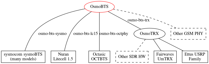
Osmo-BSC accepts Abis over IP connections from a number of different sources,
There’s a list of supported BTS hardware that can talk out of the box to the Osmo-BSC, such as the Ericsson RBS series, ip.access nanoBTS, Nokia and Siemens units and even a virtual BTS so you can simulate the connections.
If you’re using any of these premade BTS hardware options, or osmo-bts-virtual, you probably just need to setup the basics on your BTS and point it to your BSC, end of story.
The below post will touch on using common SDR hardware to act as our BTS. If you’re not using SDR hardware you can just skip ahead to the next post on BSCs.
But, if you’re in the same boat as me, without any commercial BTS / RAN hardware, we’ll be setting it up by using an SDR platforms (In my case LimeSDR) and that’s what this tutorial will focus on.
Osmo-TRX
In order to bring in a large array of SDR hardware, Osmocom have introduced Osmo-TRX, which handles the Layer 1 physical layer of the BTS, and connects to Osmo-BTS which serves as the BTS and talks Abis over IP to the MSC.
Certain hardware can talk directly to Osmo-BTS, but we’re going to rely on Osmo-TRX to act as the middleman between our SDR hardware and the BTS.
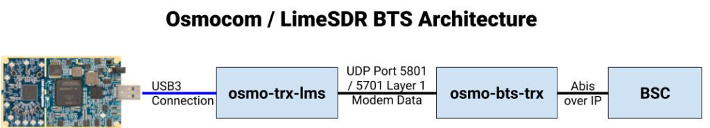
The above diagram from the Osmocom wiki shows how this fits together with generic SDR platforms, here’s how it fits together for us:
osmo-trx-lms will take care of the SDR side of the equation, pretty much serving as a modem and sending everything it gets on the Uu interface to osmo-bts-trx over UDP, and everything it receives from osmo-bts-trx over UDP it sends out the Uu interface.
osmo-bts-trx will then setup an Abis over IP connection to our BSC.
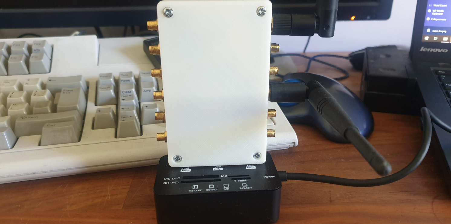
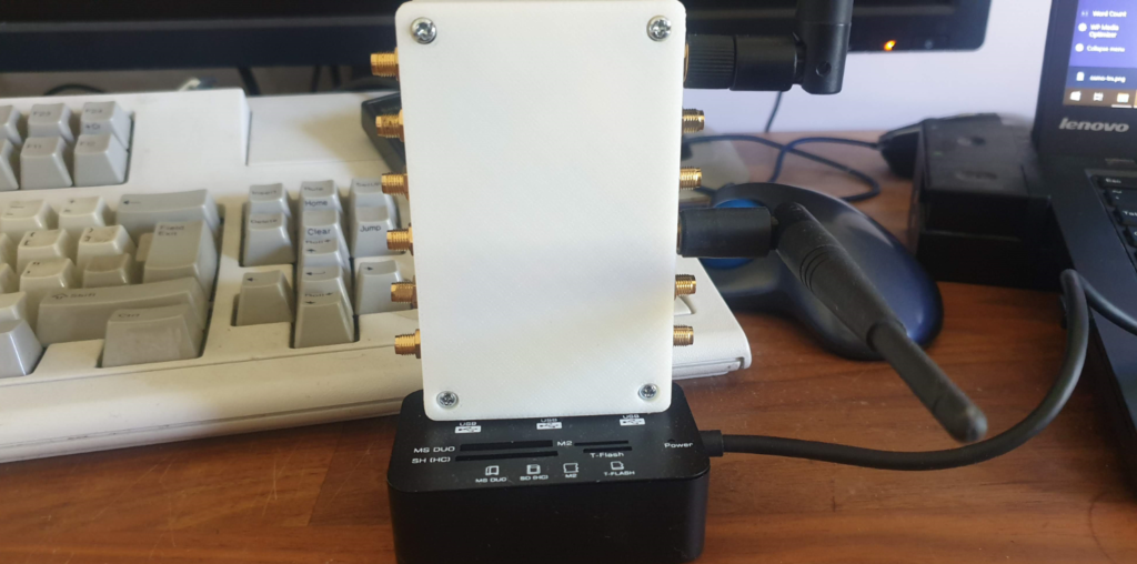
The LimeSDR
My ever growing collection of SDR hardware now includes a LimeSDR which I’ll be using for this series.
Before we can get too far we’ve got to setup the prerequisites for the LimeSDR to be able to interface with Osmo-TRX.
Osmocom now provide a binary for interfacing with LimeSDR boards directly, instead of having to use the UHD abstraction. This is a much cleaner way of interfacing with the boards and the path I’ll be taking.
Software Install
For this tutorial series I’ll be using Ubuntu 18.04 and trying where possible to use packages from Repos instead of compiling from source.
LimeSuite provides the drives and utilities for interfacing with the LimeSDR.
So now we’ve got two pieces of the puzzle, it’s time to connect the SDR to Osmo-TRX-LMS and connect Osmo-TRX-LMS to Osmo-BTS-TRX.
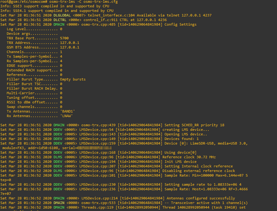
We’ll begin by running Osmo-TRX-LMS to connect to the LimeSDR and encapsulate the Uu data into UDP packets we send to Osmo-BTS-TRX.
Config files for Osmocom are installed in /etc/osmocom/ so we’ll run everything from that directory.
osmo-trx-lms -C osmo-trx-lms.cfg
If all was successful you’ll see something similar to what I’ve got below, showing Osmo-TRX-LMS has connected to the SDR and is ready to go.
But if you go scanning the airwaves now, you won’t see any data coming out of the SDR’s transmitter.
That’s because Osmo-TRX-LMS needs to connect to Osmo-BTS-TRX,
We’ll leave Osmo-TRX-LMS running, so let’s open up another session and start Osmo-BTS-TRX.
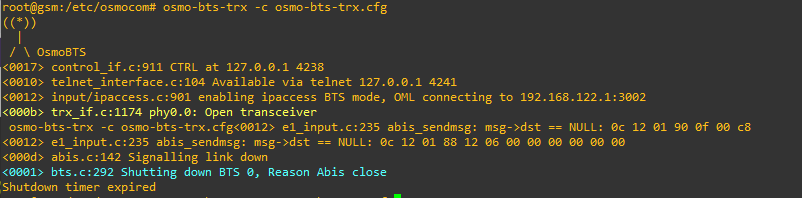
osmo-bts-trx -c osmo-bts-trx.cfg
You’ll see for starters that it’s Opened our transceiver (hooray),
You’ll see this reflected in the Osmo-TRX-LMS stdout, but it’ll show the poweroff command has been sent to it, so what gives?
Well, the answer becomes clear if you leave Osmo-BTS-TRX running for a minute or two,
Eventually the process stops, reporting:
<000d> abis.c:142 Signalling link down
<0001> bts.c:292 Shutting down BTS 0, Reason Abis close
So what’s going on? In the same way we saw our Virtual BTS shut itself down, without a connection to the BSC (Via the Abis interface) the BTS will shut itself down, as it’s not able to run on it’s own.
This took me a shamefully long time to work out that’s why it was stopping…
In our next post we’ll introduce our BSC and provision a BTS on it.
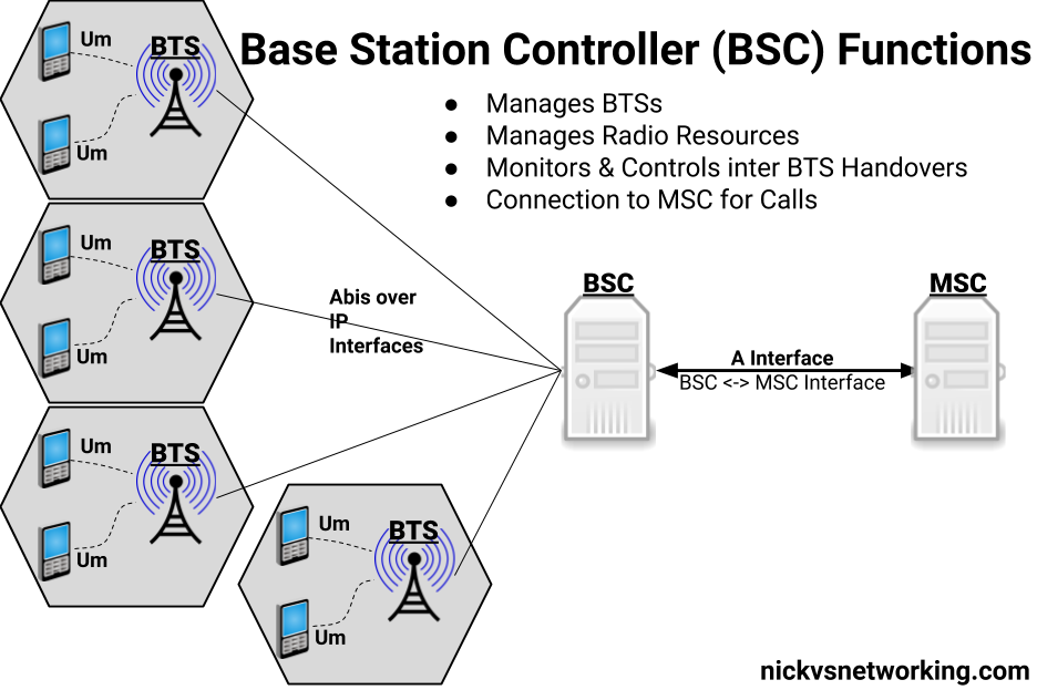
So in our last post we finished setting up a Base Transceiver Station (BTS) but it’s no use unless it can home itself to a Base Station Controller (BSC).
So what does a BSC do?
The BSC acts as a central controller for one or more BTS.
In practice this means the BSC configures most of the parameters on the BTS and brings each one up onto the air when they’re ready.
The BSC monitors measurements from users to work out when to hand off from one BTS to neighboring BTS,
The BSC also handles the allocation of radio channels and radio resources across the BTSs it manages.
In short, it does pretty much everything radio related for the BTS except transmitting and receiving data over the Air (Um) interface.
As well as managing the BTS under it, the other other equally important role of the BSC is to provide connectivity to the rest of the GSM network, by connecting to a Mobile Switching Center (MSC) which handles calls to and from our mobile subscribers and authenticating them.
By acting as a funnel of sorts, the MSC only needs a connection to each BSC instead of to each BTS (Which would be an impractically large number of connections)
Osmo BSC Install
Osmocom have their own BSC – Aptly called Osmo-BSC.
Installation is pretty straightforward, assuage you’ve got the Osmocom repo in your sources list:
apt-get install osmo-bsc
systemctl stop osmo-bsc
In order to serve the BTSs it controls, Osmo-BSC relies on connectivity to a Mobile Switching Center (MSC), which in turn connects to a HLR (Home Location Register). The BSC and MSC communicate via SS7, and the routing is done by a Signal Transfer Points (STP).
We’ll go into each of these elements in more detail, but in order to bring our BSC up in a useful way, we’ll need to install and start these applications.
We’ll talk about the MSC, the basics of SS7 / Sigtran and the HLR later in the series, but for now we’ll blindly install and start them:
We’ll come back and cover each of these elements in more detail in due course.
Osmo Config – Telnet Interactive Terminal
So now we’ve got the BSC installed we’ve pointed our BTS at the IP of the BSC, we’ll need to get osmo-bsc running and add the config for our new BTS.
Instead of working with the text file we’ll start the service and work on it through Telnet, like we would for many common network devices.
Osmo-BSC listens on port 4242, so we’ll start Osmo-BSC and connect to it via Telnet:
systemctl start osmo-bsc
telnet localhost 4242
The interface should come pretty naturally to anyone who’s spent much time setting up other network devices, a lot of the commands are similar and yes – tab completion is a thing!
We’ll start by enabling logging so we can get an idea of what’s going on:
OsmoBSC> enable
OsmoBSC# logging enable
OsmoBSC# logging filter all 1
OsmoBSC# logging color 1
Next up in a new terminal / SSH session, we’ll run our virtual BTS again;
osmo-bts-virtual -c osmo-bts-virtual.cfg
This time we’ll get a different output from the BTS when we try to start it:
root@gsm-bts:/etc/osmocom# osmo-bts-virtual -c osmo-bts-virtual.cfg
 ((*))
   |
  / \ OsmoBTS
<0010> telnet_interface.c:104 Available via telnet 127.0.0.1 4241
<0012> input/ipaccess.c:901 enabling ipaccess BTS mode, OML connecting to 127.0.0.1:3002
<0012> input/ipa.c:128 127.0.0.1:3002 connection done
<0012> input/ipaccess.c:724 received ID_GET for unit ID 4242/0/0
<0012> input/ipa.c:63 127.0.0.1:3002 lost connection with server
<000d> abis.c:142 Signalling link down
<000d> abis.c:156 OML link was closed early within 0 seconds. If this situation persists, please check your BTS and BSC configuration files for errors. A common error is a mismatch between unit_id configuration parameters of BTS and BSC.

root@gsm-bts:/etc/osmocom#
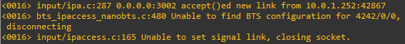
We’ll also see errors in the terminal on the BSC too:
<0016> input/ipa.c:287 0.0.0.0:3002 accept()ed new link from 10.0.1.252:39383
<0016> bts_ipaccess_nanobts.c:480 Unable to find BTS configuration for 4242/0/0, disconnecting
So what’s happening here?
Well our virtual BTS is trying to connect to our BSC, and this time it’s able to, but our BSC doesn’t have any config in place for that BTS, so the BSC has rejected the connection.
So now we’ve got to configure a the BSC to recognise our BTS.
Provisioning a new BTS in the BSC
So as to keep this tutorial generic enough for anyone to follow along, we’re first going to configure a virtual BTS in our BSC to begin with. I wrote about installing Osmo-BTS-Virtual in this post.
We can get the information about the rejected BTS connection attempt from the BSC terminal:
OsmoBSC# show rejected-bts
 Date                Site ID BTS ID IP
2020-03-29 01:32:37    4242      0      10.0.1.252
So we know the Site-ID is 4242 (we set it earlier) and the BTS ID for that site is 0, so let’s create a BTS in the BSC;
Well as we’re getting the majority of the smarts for the BTS from the BSC, we’ve got to tell the BSC all about how we want the BTS setup. (Believe it or not this is the most abridged setup I could muster.)
The type, IPA Unit ID, band and Cell Identity make up some of the parameters we need to identify the BTS (IPA Unit ID) and give it it’s basic identity parameters.
Next up in the trx 0 section we set the contents of the 8 GSM timeslots. Our first time slot we configure as CCCH+SDCCH4 meaning the first timeslot will contain the Common Control Channel and 4 Standalone dedicated control channels, used for signalling, while the reamining 7 timeslots will be used with traffic channels for full-rate speech (TCH/F).
It’s important that what we tell the BSC the capabilities of the BTS are match the actual capabilities of the BTS. For example there’s no point configuring GPRS or EDGE support on the BSC if the BTS doesn’t support it.
If you’ve got logging enabled when the BTS connects to the BSC you’ll see errors listing the features mismatch between the two.
As you can imagine there’s better options than this for adding BTS in bulk – Osmocom Control Interface exposes these functions in an API like way, but before you start on network orchestration it’s good to know the basics.
Connecting the BTS to the BSC
So let’s go ahead and connect our BTS to the BSC.
If you’ve closed the BSC terminal since we enabled logging you’ll need to enable it again:
OsmoBSC> logging enable
OsmoBSC> logging filter all 1
OsmoBSC> logging color 1
And next up we’ll try and start the BTS again:
root@gsm-bts:/etc/osmocom# osmo-bts-virtual -c osmo-bts-virtual.cfg
 ((*))
   |
  / \ OsmoBTS
<0010> telnet_interface.c:104 Available via telnet 127.0.0.1 4241
<0012> input/ipaccess.c:901 enabling ipaccess BTS mode, OML connecting to 127.0.0.1:3002
<0012> input/ipa.c:128 127.0.0.1:3002 connection done
<0012> input/ipaccess.c:724 received ID_GET for unit ID 4242/0/0
And on the BSC you’ll see roughly the same thing:
OsmoBSC#
<0016> input/ipa.c:287 0.0.0.0:3002 accept()ed new link from 127.0.0.1:40193
<0004> abis_nm.c:490 BTS1 reported variant: omso-bts-virtual
<0004> abis_nm.c:578 OC=BASEBAND-TRANSCEIVER(04) INST=(00,00,ff): BTS1: ARI reported sw[0/1]: TRX_PHY_VERSION is Unknown
<0016> input/ipa.c:287 0.0.0.0:3003 accept()ed new link from 127.0.0.1:44053
<0003> osmo_bsc_main.c:291 bootstrapping RSL for BTS/TRX (1/0) on ARFCN 0 using MCC-MNC 001-01 LAC=4242 CID=4242 BSIC=42
If you’ve made it this far, congratulations. Our virtual BTS is now connected to our BSC – If it wasn’t virtual we’d be on the air!
So in the next post we’ll setup our SDR hardware as a BTS, then provision it on the BSC, and then our cell will be on the air.
So this series of posts will focus on using Osmocom software to create a GSM network, so let’s get some Osmocom software installed, and talk about how we run and configure each network element / node.
Osmocom Packages
For this tutorial series I’ll be using Ubuntu 18.04 and trying where possible to use packages from Repos instead of compiling from source.
This will get the Osmocom key added to your package manager and the Osmocom sources in apt ready for us to install.
To get started we’ll install a virtual BTS. This virtual BTS won’t simulate the Um (air) interface, but it will simulate the Abis interface towards the BSC so we can configure this virtual BTS in our BSC.
Installation is pretty straightforward:
apt-get install osmo-bts-virtual
By default Osmocom software runs as a daemon in systemctl, we’ll disable and stop this behaviour for now so we can better understand it running in the foreground:
If you have a look in /etc/osmocom/ you’ll see .cfg files that contain our config in text files.
But that’s not the only way (or even the recommended way) that we’ll put together the config for Osmocom software, but we’ll get started by editing the config file manually.
We’ll start by setting a Unit ID of the BTS and setting the IP of the BSC.
cd /etc/osmocom/
vi osmo-bts-virtual.cfg
We’ll edit the oml remote-ip to point to the IP of the server that will run our BSC, if you’re planning on running the BTS and BSC on the same machine you can leave it as localhost (127.0.0.1).
Next up we’ll set the Unit-ID of the BTS, this identifies the BTS inside the BSC,
I’ll set it to unit-id 4242 by changing ipa unit-id 4242 0
Finally we’ll change the logging config to show everything by changing it to:
log stderr
 logging filter all 1
!
So that’s it in terms of config for our virtual BTS through text files, so we’ll save the file and try starting up osmo-bts-virtual.
osmo-bts-virtual -c osmo-bts-virtual.cfg
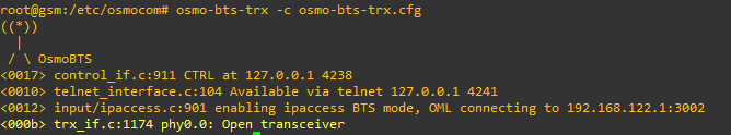
You should get a result similar to this:
root@gsm-bts:/etc/osmocom# osmo-bts-virtual -c osmo-bts-virtual.cfg
 ((*))
   |
  / \ OsmoBTS
<0010> telnet_interface.c:104 Available via telnet 127.0.0.1 4241
<0012> input/ipaccess.c:901 enabling ipaccess BTS mode, OML connecting to 127.0.0.1:3002
<000d> abis.c:142 Signalling link down
<0001> bts.c:292 Shutting down BTS 0, Reason Abis close
Shutdown timer expired

root@gsm-bts:/etc/osmocom#
So what are we seeing here?
Well Osmo-BTS-Virtual is trying to bring up it’s Abis interface but it’s not getting a connection to the the BSC (We haven’t set one up yet). No connection to a BSC means the BTS won’t go on the air as it doesn’t have any processing for itself, so it eventually times out and shuts down.
In the next post we’ll move from using osmo-bts-virtual to using a SDR to run Osmo-BTS. If you’re using commercial RAN hardware, or just playing along without any RAN, skip straight to the post on Base Station Controllers where we’ll pick up again adding our Virtual BTS to the BSC.
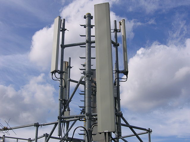
By far the most visable part of any mobile network (apart from your phone!) is the Base (Transciver) Stations.
Dotted around the countryside, on masts, towers and monopoles, whether you notice them or not, base stations are everywhere.
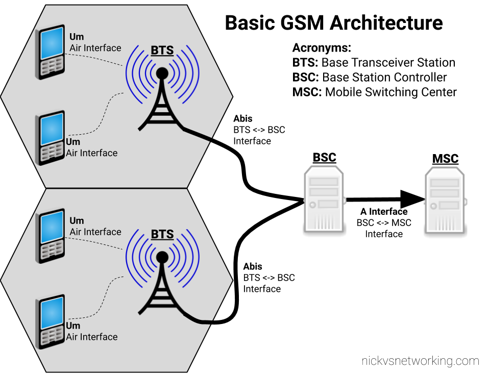
The Architecture
The RF side of LTE has an eNodeB, which is a smart device. – You connect it to a TCP/IP network, it establishes a connection with your MME(s) and away you go.
A GSM BTS (Base Transceiver Station) isn’t all that clever…
The BTS is a similar to the WiFi access points that talk to a centralised controller for all their thinking. A BTS gets most of its brains from elsewhere and essentially just handles the TX/RX of baseband data.
That elsewhere is the BSC – Base Station Controller. Each BTS connects to a BSC, and a BSC would typically control a number of BTS.
We’ll explore the BSC and it’s connections in depth, but I’ve put together a basic diagram of how everything fits together below.
Basic GSM Access Architecture
Um Interface
The Um interface is the Air Interface of GSM. It’s what takes the data and sends it out “over the air”.
There’s a lot to know about air interfaces, and I know very little. What I do know is I need to set the Um interface to use a frequency band my mobile phone supports (so I can see and connect to the network).
The Abis Interface
The fact that GSM was first deployed in 1991, explains why the Abis interface used ISDN E1/T1 TDM links to connect the Base Transceiver Stations (BTSs) to the Base Station Controller (BSC).
While now looking back you may ask why TCP/IP wasn’t used for the Abis interface, keep in mind that Windows 95 was the first version to include TCP/IP support, and that gives you an idea of the state of play. ISDN is very reliable and was well known in the telco space at that time.
I no longer have any ISDN hardware, so for me this is all going to be built using packet switched networks working as circuit switched.
Osmocom does have support for E1/T1 interfaces, so if you’ve got BTS hardware that only communicates over TDM links, that’s an option too.
GSMA never wrote a standard for taking Abis over IP, so as such each vendor has implemented it differently.
With all the brains for the BTS residing in the BSC, there’s a need to control the BTS from the BSC. The Operation and Maintenance Link (OML) is a protocol for changing certain parameters of the BTS from the BSC.
A prime example of use of the OML would be the BSC turning the BTS off/on.
We’ll see a tiny bit of OML usage in the next post, just for turning the BTS off and on.
So let’s put this into practice and setup a virtual BTS with Osmocom.
Like most people at the moment because of the lockdown I’ve got a bit more time at home than normal.
Because of this I thought I’d finally dive into GSM/UMTS and all that circuit switched tech you skip out on when getting started with LTE.
Please excuse the loving tone I use when describing some older tech, it’s a result of being a telephony tragic who gets all reminiscent thinking about the first phones they interacted with & wondered about how it all worked…
So why learn GSM?
My best friend is a translator of technical documents. In University, what’s the first language they study? Latin. Because it’s the root of so many languages.
While a lot of carriers have already switched off their GSM networks (There are no public GSM networks in Australia), the core of GSM is essentially shared with that of UMTS / 3G, which is still going to be around for the foreseeable future.
Circuit Switched Fallback (CSFB) is still common today for voice calls for a great many LTE handsets without VoLTE support. GSM powers GSM-R, the rail specific standard of GSM used across Europe. The uplink power of GSM can be up to 8 Watts (while in LTE it’s 20 dBm – 0.1W) which means it’s effective service area could be larger than 3G and 4G air interfaces.
GSM isn’t as dead as it might seem, so let’s have a Weekend at Bernie’s!
Disclaimer: Please let me know if I’ve got anything wrong! These posts will focus on the Omsocom network elements which do handle a few things the “non standard” way.
It’s great that it works from a Um interface perspective; your UE / terminal can see and connect to the network. But it’s sort of an all-in-one solution; there’s no Mobile Switching Center, Base Station Controller, Sigtran, HLR or Media Gateway; Yate ties all this up into a single easy to use package.
This gets you on the air in no time, but unfortunately you don’t get exposed to how GSM / UMTS works in the real world – real networks don’t look like YateBTS NITPC.
Enter Osmocom
Osmocom (and the Sysmocom team driving many of the projects) have done a phenomenal job of building each of the network elements I just talked about pretty much “by the book”, meaning most should interop with commercial equipment and comply to the standards.
Over the next few weeks I’ll cover setting up each of the network elements, talking about what they do and how they work, and use them to create a functional GSM network (2G / Circuit Switched) using the software from Osmocom.
Once we’ve got our network functional we’ll be adding SMS, Data (GPRS / EDGE), USSD codes and even inter-RAT handover with LTE.
For this series of posts I’ll be using a mix of hardware. At the start I’ll be using a Software Defined Radio (LimeSDR) to do the RF side of the network (BTS). Osmocom has support for a lot of common SDR hardware, so hopefully for anyone wanting to follow along at home you’ll have access to a LimeSDR or USRP.
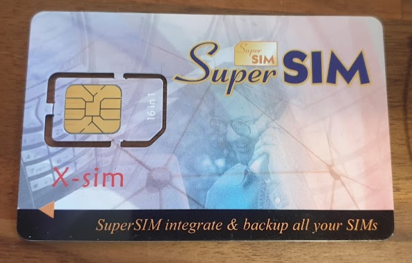
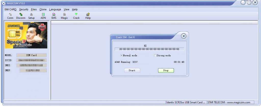
I found a “16-in-1 Super SIM X-SIM” in my SIM card drawer, I think I ordered these when I was first playing with GSM and never used it.
I was kind of curious about how these actually worked, so after some online sleuthing I found a very suspicious looking rar file, which I ended up running in a VM and mapping the Card Reader to the VM.
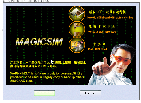
What a treat I was in for in terms of UI.
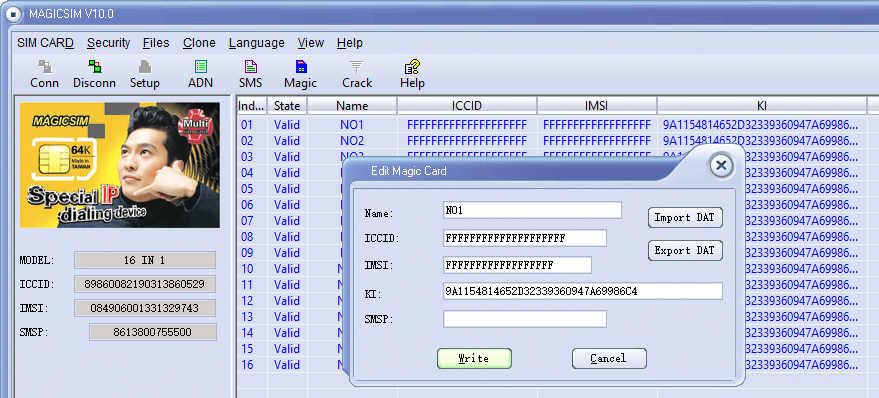
The concept is quite simple, you program a series of IMSI and K key values onto the SIM card, and then using a SIM Toolkit application, you’re able to select which IMSI / K key combination you want to use.
A neat trick, I’d love a LTE version of this for changing values on the fly, but it’d be a pretty niche item considering no operator is going to give our their K and OPc keys,
But come to think of it, no GSM operator would give out K keys, so how do you get the K key from your commercial operator?
I noticed the grayed out “Crack” icon on the menu.
After rifling through my SIM drawer I found a few really old 2G SIMs, stuck one in, reconnected and clicked “Crack” and then start.
I left it running in the background after the manual suggested it could take up to 24 hours to run through all the codes.
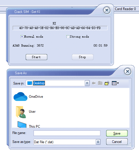
To my surprise after 2 minutes the software was requesting I save the exported data, which I did.
Then I put the 16 in 1 back in, selected Magic and then imported the cracked SIM data (IMSI, ICCID, Ki & SMSp).
By the looks of it the software is just running a brute force attack on the SIM card, and the keyspace is only so large meaning it can be reversed in.
I did a bit of research to find out if this is exploiting any clever vulnerabilities in UCCID cards, but after running some USB Pcap traces it looks like it’s just plain old brute force, which could be easily defended against by putting a pause between auth attempts on the SIM.
I’ve no idea if that’s the actual K value I extracted from the SIM – The operator that issued the SIM doesn’t even exist anymore, but I’ll add the details to the HLR of my Osmocom GSM lab and see if it matches up.
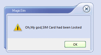
Out of curiosity I also connected some of my development USIM/ISIM/SIM cards that I can program, the software is amazing in it’s response:
I did a post yesterday on setting up YateBTS, I thought I’d cover the basic setup I had to do to get everything humming;
Subscribers
In order to actually accept subscribers on the network you’ll need to set a Regex pattern to match the prefix of the IMSI of the subscribers you want to connect to the network,
In my case I’m using programmable SIMs with MCC / MNC 00101 so I’ve put the regex pattern matching starting with 00101.
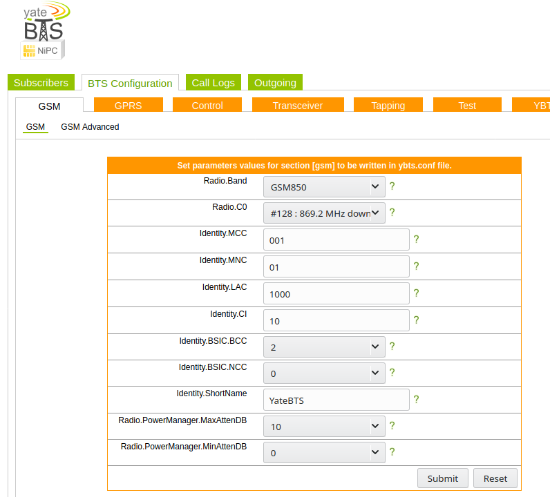
BTS Configuration
Next up you need to set the operating frequency (radio band), MNC and MCC of the network. I’m using GSM850,
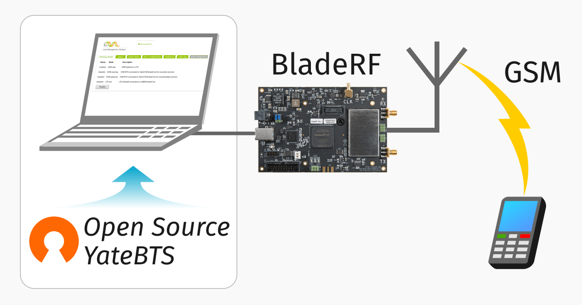
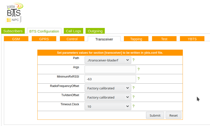
Next up we’ll need to set the device we’re going to use for the TX/RX, I’m using a BladeRF Software Defined Radio, so I’ve selected that from the path.
Optional Steps
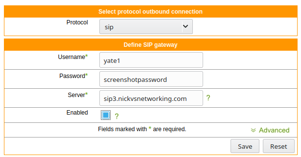
I’ve connected Yate to a SIP trunk so I can make and receive calls,
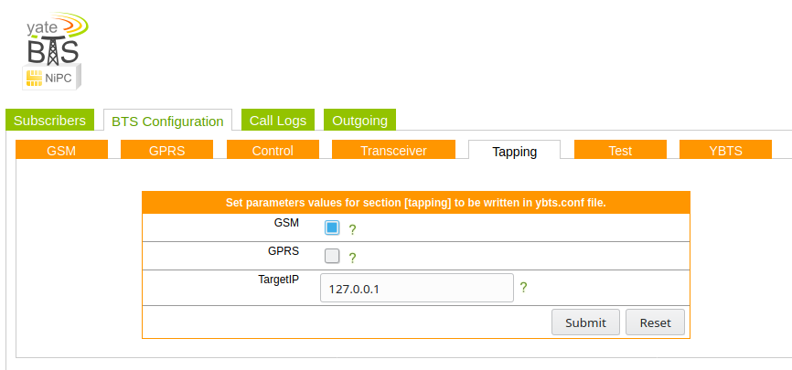
I’ve also put a tap on the GSM signaling, so I can see what’s going on, to access it just spin up Wireshark and filter for GSMMAP
A lot of the Yate tutorials are a few years old, so I thought I’d put together the steps I used on Ubuntu 18.04:
Installing Yate
apt-get install subversion autoconf build-essential
cd /usr/src svn checkout http://voip.null.ro/svn/yate/trunk yate
cd yate
./autogen.sh
./configure
make
make install-noapi
I wrote about using Ansible to automate Kamailio config management, Ansible is great at managing VMs or bare metal deployments, but for Containers using Docker to build and manage the deployments is where it’s at.
I’m going to assume you’ve got Docker in place, if not there’s heaps of info online about getting started with Docker.
The Dockerfile
The Kamailio team publish a Docker image for use, there’s no master branch at the moment, so you’ve got to specify the version; in this case kamailio:5.3.3-stretch.
Once we’ve got that we can start on the Dockerfile,
For this example I’m going to include
#Kamailio Test Stuff
FROM kamailio/kamailio:5.3.3-stretch

#Copy the config file onto the Filesystem of the Docker instance
COPY kamailio.cfg /etc/kamailio/

#Print out the current IP Address info
RUN ip add

#Expose port 5060 (SIP) for TCP and UDP
EXPOSE 5060
EXPOSE 5060/udp
Once the dockerfile is created we can build an image,
docker image build -t kamtest:0.1 .
And then run it,
docker run kamtest:0.1
Boom, now Kamailio is running, with the config file I pushed to it from my Dockerfile directory,
Now I can setup a Softphone on my local machine and point it to the IP of the Docker instance and away we go,
Where the real power here comes in is that I can run that docker run command another 10 times, and have another 10 Kamailio instannces running.
Tie this in with Kubernetes or a similar platform and you’ve got a way to scale and manage upgrades unlike anything you’d get on Bare Metal or VMs.
I had a few headaches getting the example P-CSCF example configs from the Kamailio team to run, recent improvements with the IPsec support and code evolution meant that the example config just didn’t run.
So, after finally working out the changes I needed to make to get Kamailio to function as a P-CSCF, I took the plunge and made my first pull request on the Kamailio project.