This one was a bit of a head scratcher for me, but I’m always glad to learn something new.
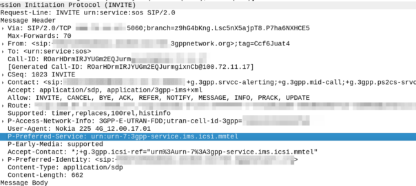
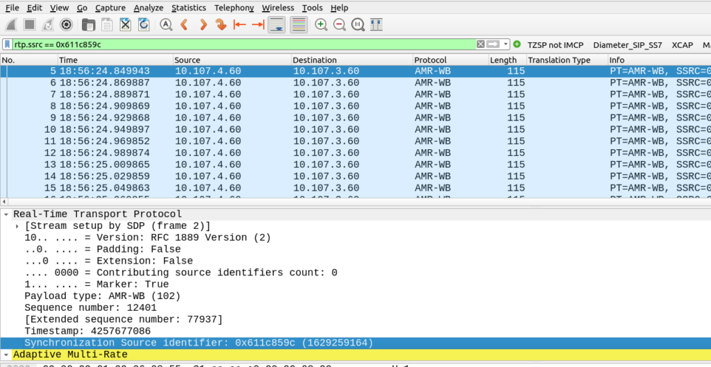
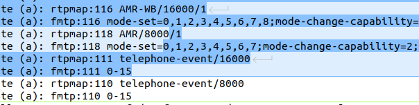
The handset made a VoLTE call, and it’s SDP offer shows it can support AMR and AMR-WB:
        Media Attribute (a): rtpmap:116 AMR-WB/16000/1
        Media Attribute (a): fmtp:116 mode-set=0,1,2,3,4,5,6,7,8;mode-change-capability=2;max-red=220
        Media Attribute (a): rtpmap:118 AMR/8000/1
        Media Attribute (a): fmtp:118 mode-set=0,1,2,3,4,5,6,7;mode-change-capability=2;max-red=220
        Media Attribute (a): rtpmap:111 telephone-event/16000
        Media Attribute (a): fmtp:111 0-15
Okay, that’s pretty normal, I can see we have the mode-set parameter defined, which indicates what modes the handset supports for each codec.
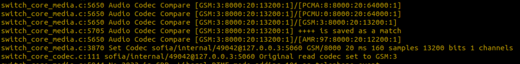
In our problem scenario, the Media Gateway that the call was sent to responded with this SDP answer:
        Media Description, name and address (m): audio 24504 RTP/AVP 118 110
        Media Attribute (a): rtpmap:118 AMR/8000
        Media Attribute (a): fmtp:118 mode-set=7
        Media Attribute (a): rtpmap:110 telephone-event/8000
        Media Attribute (a): fmtp:110 0-15
        Media Attribute (a): ptime:20
        Media Attribute (a): sendrecv
        [Generated Call-ID: FA163E564B37-f4d-98f56700-735d25-65357ee0-9c488]
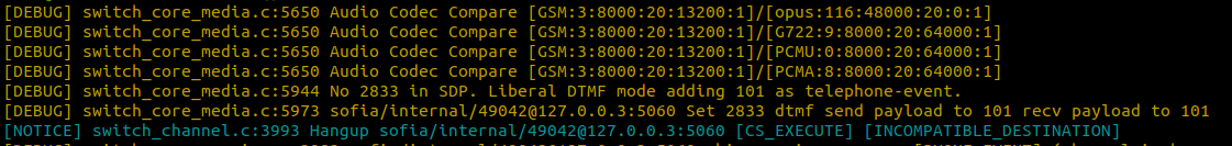
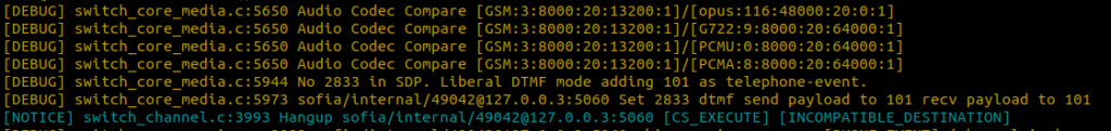
But we got an error about not available codecs and the call drops, what gives?
Both sides support AMR (Only the phone supports AMR-WB), and the Media Gateway, as the answerer, supports mode-set 7, which is supported by the UE, so we should be good?

Well, not quite:
If mode-set is specified, it MUST be abided, and frames encoded with modes outside of the subset MUST NOT be sent in any RTP payload or used in codec mode requests. If not present, all codec modes are allowed for the payload type.
RFC 4867 – RTP Payload Format for AMR and AMR-WB
Okay, I get it, the answerer (media gateway) only supports mode 7, but the UE supports all the modes, so we should be fine right?
Well, no.
Section 8.3.1 in the RFC goes on to say in the Offer-Answer Model Considerations:
The parameter [mode-set] is bi-directional, i.e., the restricted set applies to media both to be received and sent by the declaring entity. If a mode set was supplied in the offer, the answerer SHALL return the mode-set unmodified or reject the payload type. However, the answerer is free to choose a mode-set in the answer only if no mode-set was supplied in the offer for a unicast two-peer session.
And there is our problem, and why the call is getting rejected.
The Media Gateway (the answerer in this scenario) is sending back the mode-set it supports (7) but as the UE / handset (offerer) included the mode-set, the Media Gateway should either respond with the same mode set (if it supported all the requested modes) or reject it.
Instead we’re seeing the Media Gateway repond with the mode set, which it supports, which it should not do: The Media Gateway should either return the same mode-set (unmodified / unchanged) or reject it.
And boom, another ticket to another vendor…