Tag Archives: EPC

IMTx: NET02x (4G Network Essentials) – Management of Data Flows – 5/6. S1AP Connection

These are my lecture notes from IMT’s NET02x (4G Network Essentials) course, I thought I’d post them here as they may be useful to someone. You can find my complete notes here.

Each MME can manage millions of UEs.

To handle this load the requirements of each subscriber for the MME must be as minimal and simple as possible so as to scale easily.

For each UE in the network a connection is setup between the UE and the MME.

This is done over the S1-AP’s Control Plane interface (sometimes calls S1-Control Plane or S1-CP) which carries control plane data to & from the UE via the eNB to the MME.

S1-CP is connection-oriented, meaning each UE has it’s own connection to the MME, so there are as many S1-CP connections to the MME as UE’s connected.

Each of these S1-CP connections is identified by a pair of unique connection IDs. The eNB keeps track of the connection IDs for each UE connected and hands this information off each time the UE moves to a different eNB.

The eNB keeps a lookup table between the RNTI of the UE and the LCID – the Logical Channel Identifier. This means that the eNB knows the sent and received ID of the S1-CP connection for each UE, and is able to translate that into the RNTI and LCID used to send the data over the air interface to the UE.

S1-CP Connect (Attach Procedure)

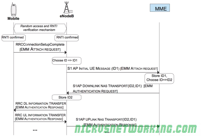
As we discussed in radio interfaces, when a UE connects to the network it is assigned an RNTI to identify it on the radio interface and allocate radio resources to it.

Once the RNTI is confirmed by both the eNB and the UE, a EMM Attach Request, which is put into an RRC Message called RRCConnectionSetupComplete.

The eNB must next choose a serving MME for this UE. It picks one based on it’s defined logic, and sends a S1-AP Intial UE Message (EMM Attach Request) to the MME along with the eNB’s connection identity assigned for this connection.

The MME stores the connection identity assigned by the eNB and chooses it’s own connection identity for it’s side, and sends back an S1AP Downlink NAS Transport response with both connection identities and the response for the attach request (This will be an EMM Authentication Request).

The eNB then stores the connection identity pair and the associated RNTI and LCID for the UE, and forwards the EMM Authentication Request to the RNTI of the UE via RRC.

The UE will pass the authentication challenge input parameters to the USIM which will generate a response. The UE will send the output of this response in a EMM Authentication Responseto the eNB, which will look at the RNTI and LCID received and consult the table to find the Connection Identifiers and IP of the serving MME for this UE.
S1AP Connect procedure

IMTx: NET02x (4G Network Essentials) – Management of Data Flows – 4. Transmitting Packets in a Tunnel

These are my lecture notes from IMT’s NET02x (4G Network Essentials) course, I thought I’d post them here as they may be useful to someone. You can find my complete notes here.

Establishing a GTP Tunnel

When a new tunnel is setup between two nodes, GTP-C will be used to setup the tunnel and the both ends of the tunnel will allocate a their own locally unique TEID to the tunnel.

Let’s take a look at setting up a GTP tunnel between a S-GW and a P-GW, initiated by the S-GW.

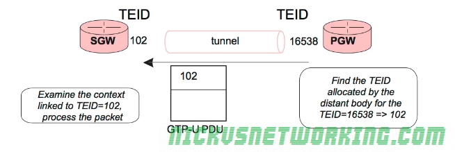
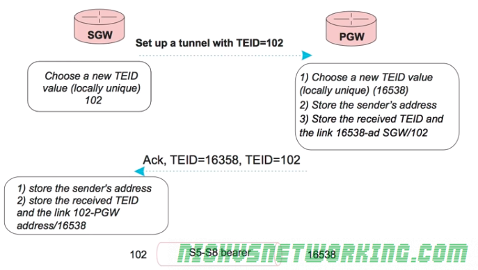
The process will start with the S-GW sending the P-GW a GTP-C tunnel establishment request and include the TEID the S-GW has allocated for it’s end of the tunnel (using TEID 102 in this example), sent from the S-GW to the P-GW.

The P-GW will receive this packet. When it does it will allocate a new TEID for this tunnel for it’s side (In this case it’s 16538), store the sender’s address and received TEID, and link local TEID 16538 with S-GW/102.

An ACK is sent from the P-GW to the S-GW with both TEID values.

Finally the S-GW stores the senders’ address, the received TEID and the link 102-PGW address 16538.


Now the exchange is complete the S-GW and the P-GW each know the TEID of it’s local side of the tunnel, and the remote side of the tunnel.

TEID Management Tables

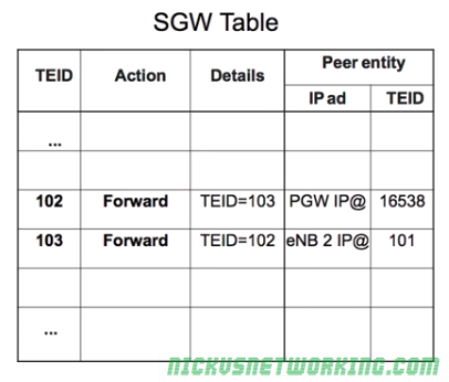
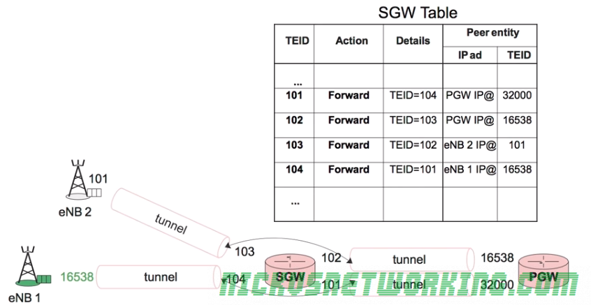
After GTP tunnels are setup a management table is populated defining the forward rules for that traffic.

For example a packet coming in on TEID 103 would, according to the table forward to TEID 102. TEID 102 sends traffic to the P-GW’s IP using remote TEID 16538.

The same rules for uplink are applied for downlink.

Each tunnel has pair of TEIDs a local TEID and a remote TEID.

Because it’s such a simple table it can be updated very easily and scales well.

Different QoS parameters can be assigned to each tunnel, called a data bearer.

IMTx: NET02x (4G Network Essentials) – Management of Data Flows – 3. Identifying & Managing Tunnels

These are my lecture notes from IMT’s NET02x (4G Network Essentials) course, I thought I’d post them here as they may be useful to someone. You can find my complete notes here.

As we’ve talked about traffic to and from UEs is encapsulated in GTP-U tunnels, with the idea that by encapsulating data destined for a UE it can be routed to the correct destination (eNB serving UE) transparently and efficiently.

As all traffic destined for a UE will come to the P-GW, the P-GW must be able to quickly determine which eNB and S-GW to send the encapsulated data too.

The encapsulated data is logically grouped into tunnels between each node.

A GTP tunnel exists between the S-GW and the P-GW, another GTP tunnel exists between the S-GW and the eNB.

Each tunnel between the eNB and the S-GW, and each tunnel between S-GW and P-GW, is allocated a unique 32 bit value called a Tunnel Endpoint Identifier (TEID) allocated by the node that corresponds to each end of the tunnel and each TEID is locally unique to that node.

For each packet of user data (GTP-U) sent through a GTP tunnel the TEID allocated by the receiver is put in the GTP header by the sender.

The destinations of the tunnels can be updated, for example if a UE moves to a different eNB, the tunnel between the S-GW and the eNB can be quickly updated to point at the new eNB.

If the UE moves to a different eNB only the tunnel between the S-GW and the eNB needs to be updated

Each end of the tunnel is associated with a TEID, and each time a GTP packet is sent through the tunnel it includes the TEID of the remote end (reciever) in the GTP header.

IMTx: NET02x (4G Network Essentials) – Management of Data Flows – 2. GTP Protocol

These are my lecture notes from IMT’s NET02x (4G Network Essentials) course, I thought I’d post them here as they may be useful to someone. You can find my complete notes here.

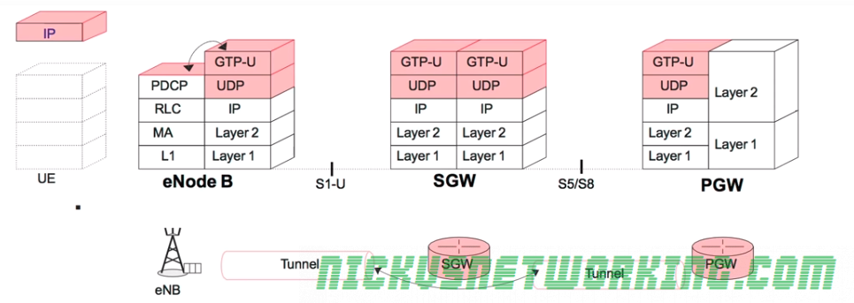
When a packet arrives from an external network, like the internet, it is routed to the P-GW.

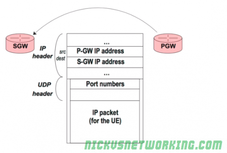
The P-GW takes this packet and places it in another IP packet (encapsulates it) and then forwards the encapsulated data to the Serving-Gateway.

The S-GW then takes the encapsulated data it just recieved and sends it on inside another IP packet to the eNB.

The encapsulated data sent from the P-GW to the S-GW, and the S-GW to the eNB, is carried by UDP, even if the traffic inside is TCP.

Communication between these elements can be done using internal addressing, and this addressing information will never be visible to the UE or the external networks, and only the P-GW needs to be reachable from the external networks.

This encapsulation is done using GTP – the GPRS Tunneling Protocol.

Specifically IP traffic to and from the UE is contained in GTP-U (User data) packets.

The control data for GTP is contained in GTP-C packets, which sets up tunnels for the GTP traffic to flow through (more on that later).

To summarize, user IP packets are encapsulated into GTP-U packets, which are a transported by UDP between the different nodes (S-GW and eNB)

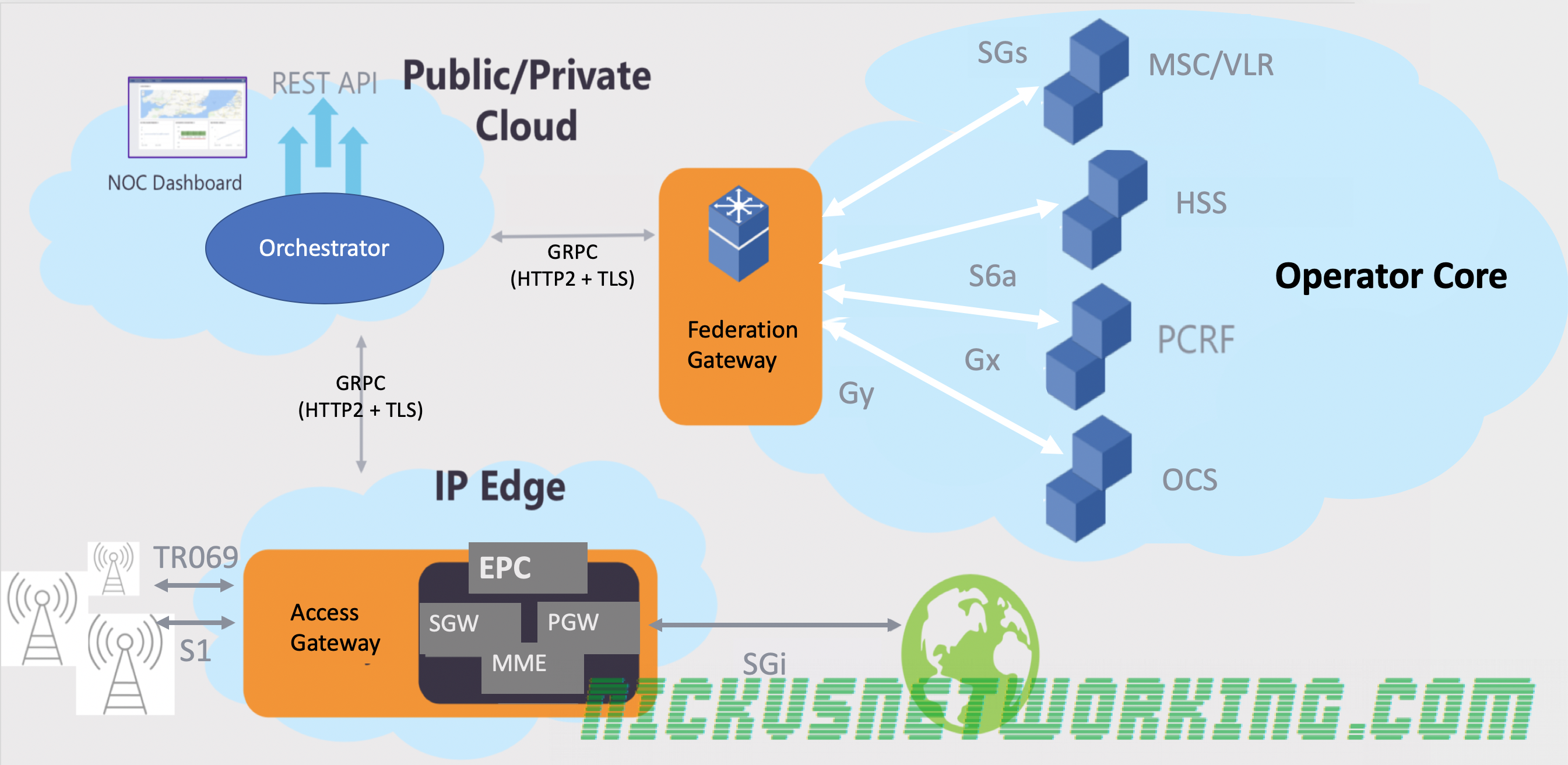
Magma – Facebook’s Open Source LTE / 4G EPC/OSS Platform

In February Facebook announced they’d open sourced their Magma project,

Magma provides a software-centric distributed mobile packet core and tools for automating network management.

Open-sourcing Magma to extend mobile networks

Magma’s modular software based architecture means you can scale up extra resources as needed, with no need to have physical hardware to run your EPC.

(Cisco’s Ultra Packet Core does have a virtualisation option, but it’s not cheap)

I got pretty excited by this, so I’ve ordered myself an eNodeB (Just a Picocell), a pile of USIMs, programmer and started installing an environment.

In the past I’ve used srsEPC and NextEPC and software-defined radio hardware (BladeRF) to run LTE stuff, so I’m looking forward to seeing if I can implement parts of them into Magma, and also eventually use Kamailio’s IMS modules to implement an IMS core and run VoLTE.

So let’s install Magma, explore it and lurk on the Discord, all while we kill time waiting for hardware to arrive!

Wireshark trace showing a "401 Unauthorized" Response to an IMS REGISTER request, using the AKAv1-MD5 Algorithm

All About IMS Authentication (AKAv1-MD5) in VoLTE Networks

I recently began integrating IMS Authentication functions into PyHSS, and thought I’d share my notes / research into the authentication used by IMS networks & served by a IMS capable HSS.

There’s very little useful info online on AKAv1-MD5 algorithm, but it’s actually fairly simple to understand.

RFC 2617 introduces two authentication methods for HTTP, one is Plain Text and is as it sounds – the password sent over the wire, the other is using Digest scheme authentication. This is the authentication used in standard SIP MD5 auth which I covered ages back in this post.

Authentication and Key Agreement (AKA) is a method for authentication and key distribution in a EUTRAN network. AKA is challenge-response based using symmetric cryptography. AKA runs on the ISIM function of a USIM card.

I’ve covered the AKA process in my post on USIM/HSS authentication.

The Nonce field is the Base64 encoded version of the RAND value and concatenated with the AUTN token from our AKA response. (Often called the Authentication Vectors).

That’s it!

It’s put in the SIP 401 response by the S-CSCF and sent to the UE. (Note, the Cyperhing Key & Integrity Keys are removed by the P-CSCF and used for IPsec SA establishment.

Wireshark trace showing a "401 Unauthorized" Response to an IMS REGISTER request, using the AKAv1-MD5 Algorithm
Click for Full Size version of this image