Kamailio is a great SIP proxy, but sometimes you might want to see requests originate from Kamailio.
While this isn’t typical proxy behaviour, RFC definitions of a proxy and technical requirements are often two different things. The UAC module allows us to use Kamailio to act as a User Agent Client instead of just a UAS.
There’s one feature I won’t cover in this post, and that’s initiating and outbound SIP Registration using the UAC module, that will get a post of it’s own in the not to distant future.
You may already be sort of using Kamailio is a UAC, if you’re using Dispatcher and sending SIP Pings, then Kamailio is sending SIP OPTIONS messages to the dispatcher destinations. If you’re using the NAT module and sending Keepalives, then you’re also using Kamailio as a UAC. The only difference is the Dispatcher and NAT Helper modules do this for us, and we’re going to originate our own traffic.
There’s a bit of a catch here, when Kamailio receives a request it follows a set of logic and does something with that request. We’re going to remain constrained by this for our example, just to keep things simple.
So let’s work on an example, if a user on our network dials a call to an emergency services number, we’ll send a text message to my IP phone to let me know who’s dialed the emergency services number.
So to start with we’ll need to load the Kamailio UAC module, using LoadModule as we would with any other module:
loadmodule "uac.so"
If you’re working on the default config file that ships with Kamailio you’ll probably have to change how record routing is handled to support UAC,
modparam("rr", "append_fromtag", 1)
Now we should have UAC support added in Kamailio, I’m going to do a bare bones example of the routing logic below, but obviously if you wanted to put this into practice in real life you’d want to actually route the SIP INVITE to an emergency services destination.
First we’ll need to find if the request is an INVITE with the Request URI to an emergency services number, I’ve programmed this in with the Australian emergency services numbers:
if(is_method("INVITE") && ($rU == "000" or $tU == "112" or $tU == "116")){
  #Matches any INVITEs with the Request URI to Address as 000, 112 or 116
  xlog("Emergency call from $fU to $rU (Emergency number) CSeq is $cs ");
}
Now calls to 000, 112 or 116 will see the alert apear in Xlog:
07:22:41 voice-dev3 /usr/sbin/kamailio[10765]: ERROR: : Emergency call from Test to 112 (Emergency number)
So next up we need to handle the sending a SIP MESSAGE request to my IP phone on the IP 10.0.1.5 – You’re probably thinking we could use the Registrar module to lookup my registered IP address, and you’re right, but to keep things simple I’m just hardcoding it in.
So to keep our routing neat we’ll send calls to the route route(“EmergencyNotify”); and so the demo works I’ll send back a 200 OK and exit – In real life you’d want to handle this request and forward it onto emergency services.
if(is_method("INVITE") && ($rU == "000" or $tU == "112" or $tU == "116")){
#Matches any INVITEs with the Request URI to Address as 000, 112 or 116
  xlog("Emergency call from $fU to $rU (Emergency number) CSeq is $cs ");
  route("EmergencyNotify");
  #You obviously would want this to route to an emergency services destination...
  sl_reply("200", "ok");
  exit;
}

if(is_method("INVITE")){
  #Matches everything else
  xlog("Just a regular call from $fU to $rU");
}
Obviously we need to now create a route called route[“EmergencyNotify”]{ } where we’ll put our UAC logic.
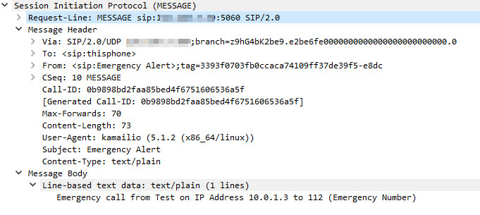
For the UAC module we need to craft the SIP Request we’re going to send; we’re going to be sending a SIP MESSAGE request,
So now we’ve sort of put it all together, when a call comes into an emergency destination, like 000, the route EmergencyNotify is called which sends a SIP MESSAGE request to my IP Phone to alert me.
When a caller dials 000 I can see Kamailio sends a SIP MESSAGE to my IP Phone:
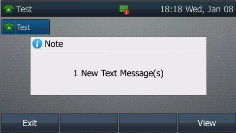
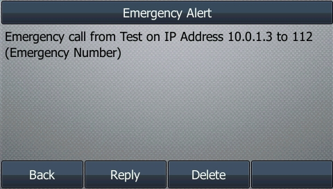
Let’s have a look at how this looks on my IP Phone:
For most Voice / Telco engineers IPsec is a VPN technology, maybe something used when backhauling over an untrusted link, etc, but voice over IP traffic is typically secured with TLS and SRTP.
IMS / Voice over LTE handles things a bit differently, it encapsulates the SIP & RTP traffic between the UE and the P-CSCF in IPsec Encapsulating Security Payload (ESP) payloads.
In this post we’ll take a look at how it works and what it looks like.
It’s worth noting that Kamailio recently added support for IPsec encapsulation on a P-CSCF, in the IMS IPSec-Register module. I’ll cover usage of this at a later date.
The Message Exchange
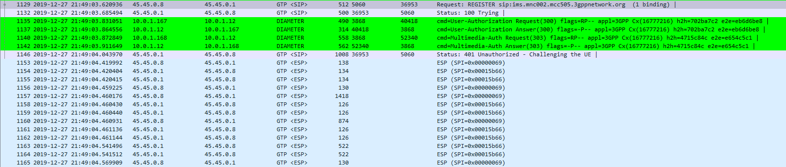
The exchange starts off looking like any other SIP Registration session, in this case using TCP for transport. The UE sends a REGISTER to the Proxy-CSCF which eventually forwards the request through to a Serving-CSCF.
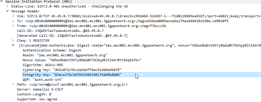
This is where we diverge from the standard SIP REGISTER message exchange. The Serving-CSCF generates a 401 Unauthorized response, containing an authentication challenge in the WWW-Authenticate header, and also a Ciphering Key & Integrity Key (ck= and ik=) also in the WWW-Authenticate header.
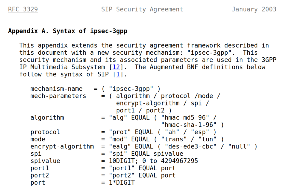
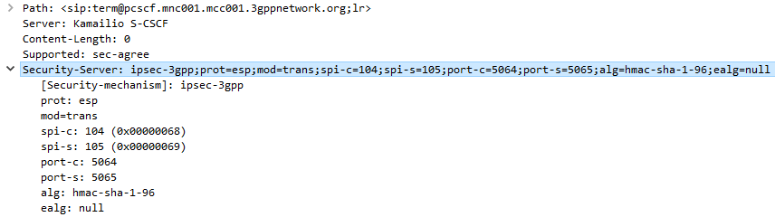
The Serving-CSCF sends the Proxy-CSCF the 401 response it created. The Proxy-CSCF assigns a SPI for the IPsec ESP to use, a server port and client port and indicates the used encryption algorithm (ealg) and algorithm to use (In this case HMAC-SHA-1-96.) and adds a new header to the 401 Unauthorized called Security–Server header to share this information with the UE.
The Proxy-CSCF also strips the Ciphering Key (ck=) and Integrity Key (ik=) headers from the SIP authentication challenge (WWW-Auth) and uses them as the ciphering and integrity keys for the IPsec connection.
Finally after setting up the IPsec server side of things, it forwards the 401 Unauthorized response onto the UE.
Upon receipt of the 401 response, the UE looks at the authentication challenge.
If the network is considered authenticated by the UE it generates a response to the Authentication Challenge, but it doesn’t deliver it over TCP. Using the information generated in the authentication challenge the UE encapsulates everything from the network layer (IPv4) up and sends it to the P-CSCF in an IPsec ESP.
Communication between the UE and the P-CSCF is now encapsulated in IPsec.
Wireshark trace of IPsec IMS Traffic between UE and P-CSCF
When learning to use Kamailio you might find yourself thinking about if you really want to learn to write a Kamailio configuration file, which is another weird scripting language to learn to achieve a task.
Enter KEMI – Kamailio Embedded Interface. KEMI allows you to abstract the routing logic to another programing language. In layman’s terms this means you can write your routing blocks, like request_route{}, reply_route{}, etc, in languages you already know – like Lua, JavaScript, Ruby – and my favorite – Python!
Why would you use KEMI?
Write in a language you already know;
You don’t need to learn how to do write complex routing logic in Kamailio’s native scripting language, you can instead do it in a language you’re already familiar with, writing your Routing Blocks in another programming language.
Change Routing on the Fly;
By writing the routing logic in KEMI allows you to change your routing blocks without having to restart Kamailio, something you can’t do with the “native” scripting language – This means you can change your routing live.
Note: This isn’t yet in place for all languages – Some still require a restart.
Leverage your prefered language’s libraries;
While Kamailio’s got a huge list of modules to interface with a vast number of different things, the ~200 Kamailio modules don’t compare with the thousands of premade libraries that exist for languages like Python, Ruby, JavaScript, etc.
Prerequisites
We’ll obviously need Kamailio installed, but we’ll also need the programming language we want to leverage setup (fairly obvious).
Configuring Kamailio to talk to KEMI
KEMI only takes care of the routing of SIP messages inside our routing blocks – So we’ve still got the Kamailio cfg file (kamailio.cfg) that we use to bind and setup the service as required, load the modules we want and configure them.
Essentially we need to load the app for the language we use, in this example we’ll use app_python3.so and use that as our Config Engine.
IPsec ESP can be used in 3 different ways on the Gm interface between the Ue and the P-CSCF:
Integrity Protection – To prevent tampering
Ciphering – To prevent inception / eavesdropping
Integrity Protection & Ciphering
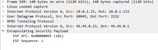
On Wireshark, you’ll see the ESP, but you won’t see the payload contents, just the fact it’s an Encapsulated Security Payload, it’s SPI and Sequence number.
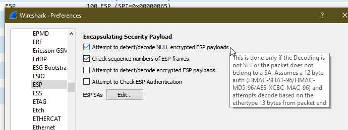
By default, Kamailio’s P-CSCF only acts in Integrity Protection mode, meaning the ESP payloads aren’t actually encrypted, with a few clicks we can get Wireshark to decode this data;
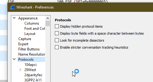
Just open up Wireshark Preferences, expand Protocols and jump to ESP
Now we can set the decoding preferences for our ESP payloads,
In our case we’ll tick the “Attempt to detect/decode NULL encrypted ESP payloads” box and close the box by clicking OK button.
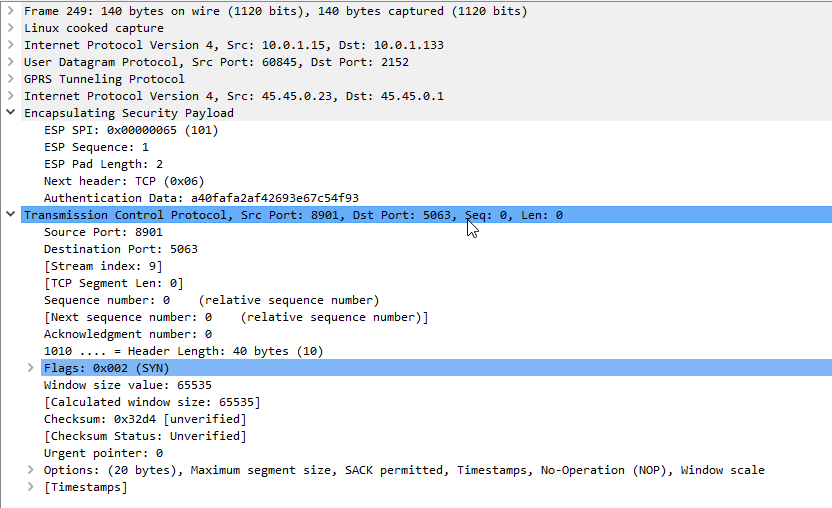
Now Wireshark will scan through all the frames again, anything that’s an ESP payload it will attempt to parse.
Now if we go back to the ESP payload with SQN 1 I showed a screenshot of earlier, we can see the contents are a TCP SYN.
Now we can see what’s going on inside this ESP data between the P-CSCF and the UE!
As a matter of interest if you can see the IK and CK values in the 401 response before they’re stripped you can decode encrypted ESP payloads from Wireshark, from the same Protocol -> ESP section you can load the Ciphering and Integrity keys used in that session to decrypt them.
On top of plain vanilla RFC3261, there’s a series of “Extension” methods added to SIP to expand it’s functionality, common extension methods are INFO, MESSAGE, NOTIFY, PRACK and UPDATE. Although now commonplace, of these is not defined in RFC3261 so is considered an “extension” to SIP.
It’s worth just pausing here to reiterate we’re not talking extensions like in a PBX context, like extra phones, we’re talking extensions like you’d add to a house, like extra functionality.
A SIP client can request functionality from a server (UAC to a UAS), if the server does not have support for that functionality, it can reject the session on those grounds and send back a response indicating it doesn’t know how to handle that extension, like a 420 Bad Extension – Bad SIP Protocol Extension used, not understood by the server. Response.
So clients can determine what functionality a server doesn’t support if it rejects the request, but there was no way to see what functionality the server does support, and what functionality the client requires.
If a UAC or UAS requires support for an extension – For example a Media Gateway has to understand PRACK, it can use the Require header to specify the request should be rejected if support for the listed extensions is not provided.
These headers are most commonly seen in SIP OPTIONS requests.
Kamailio is generally thought of as a SIP router, but it can in fact handle Diameter signaling as well.
Everything to do with Diameter in Kamailio relies on the C Diameter Peer and CDP_AVP modules which abstract the handling of Diameter messages, and allow us to handle them sort of like SIP messages.
CDP on it’s own doesn’t actually allow us to send Diameter messages, but it’s relied upon by other modules, like CDP_AVP and many of the Kamailio IMS modules, to handle Diameter signaling.
Before we can start shooting Diameter messages all over the place we’ve first got to configure our Kamailio instance, to bring up other Diameter peers, and learn about their capabilities.
C Diameter Peer (Aka CDP) manages the Diameter connections, the Device Watchdog Request/Answers etc, all in the background.
We’ll need to define our Diameter peers for CDP to use so Kamailio can talk to them. This is done in an XML file which lays out our Diameter peers and all the connection information.
In our Kamailio config we’ll add the following lines:
This will load the CDP modules and instruct Kamailio to pull it’s CDP info from an XML config file at /etc/kamailio/diametercfg.xml
Let’s look at the basic example given when installed:
<?xml version="1.0" encoding="UTF-8"?>
<!--

 DiameterPeer Parameters
  - FQDN - FQDN of this peer, as it should apper in the Origin-Host AVP
  - Realm - Realm of this peer, as it should apper in the Origin-Realm AVP
  - Vendor_Id - Default Vendor-Id to appear in the Capabilities Exchange
  - Product_Name - Product Name to appear in the Capabilities Exchange
  - AcceptUnknownPeers - Whether to accept (1) or deny (0) connections from peers with FQDN
    not configured below
  - DropUnknownOnDisconnect - Whether to drop (1) or keep (0) and retry connections (until restart)
    unknown peers in the list of peers after a disconnection.
  - Tc - Value for the RFC3588 Tc timer - default 30 seconds
  - Workers - Number of incoming messages processing workers forked processes.
  - Queue - Length of queue of tasks for the workers:
     - too small and the incoming messages will be blocked too often;
     - too large and the senders of incoming messages will have a longer feedback loop to notice that
     this Diameter peer is overloaded in processing incoming requests;
     - a good choice is to have it about 2 times the number of workers. This will mean that each worker
     will have about 2 tasks in the queue to process before new incoming messages will start to block.
  - ConnectTimeout - time in seconds to wait for an outbound TCP connection to be established.
  - TransactionTimeout - time in seconds after which the transaction timeout callback will be fired,
    when using transactional processing.
  - SessionsHashSize - size of the hash-table to use for the Diameter sessions. When searching for a
    session, the time required for this operation will be that of sequential searching in a list of
    NumberOfActiveSessions/SessionsHashSize. So higher the better, yet each hashslot will consume an
    extra 2xsizeof(void*) bytes (typically 8 or 16 bytes extra).
  - DefaultAuthSessionTimeout - default value to use when there is no Authorization Session Timeout
  AVP present.
  - MaxAuthSessionTimeout - maximum Authorization Session Timeout as a cut-out measure meant to
  enforce session refreshes.

 -->
<DiameterPeer
        FQDN="pcscf.ims.smilecoms.com"
        Realm="ims.smilecoms.com"
        Vendor_Id="10415"
        Product_Name="CDiameterPeer"
        AcceptUnknownPeers="0"
        DropUnknownOnDisconnect="1"
        Tc="30"
        Workers="4"
        QueueLength="32"
        ConnectTimeout="5"
        TransactionTimeout="5"
        SessionsHashSize="128"
        DefaultAuthSessionTimeout="60"
        MaxAuthSessionTimeout="300"
>

        <!--
                Definition of peers to connect to and accept connections from. For each peer found in here
                a dedicated receiver process will be forked. All other unkwnown peers will share a single
                receiver. NB: You must have a peer definition for each peer listed in the realm routing section
        -->
        <Peer FQDN="pcrf1.ims.smilecoms.com" Realm="ims.smilecoms.com" port="3868"/>
        <Peer FQDN="pcrf2.ims.smilecoms.com" Realm="ims.smilecoms.com" port="3868"/>
        <Peer FQDN="pcrf3.ims.smilecoms.com" Realm="ims.smilecoms.com" port="3868"/>
        <Peer FQDN="pcrf4.ims.smilecoms.com" Realm="ims.smilecoms.com" port="3868"/>
        <Peer FQDN="pcrf5.ims.smilecoms.com" Realm="ims.smilecoms.com" port="3868"/>
        <Peer FQDN="pcrf6.ims.smilecoms.com" Realm="ims.smilecoms.com" port="3868"/>

        <!--
                Definition of incoming connection acceptors. If no bind is specified, the acceptor will bind
                on all available interfaces.
        -->
        <Acceptor port="3868"  />
        <Acceptor port="3869" bind="127.0.0.1" />
        <Acceptor port="3870" bind="192.168.1.1" />

        <!--
                Definition of Auth (authorization) and Acct (accounting) supported applications. This
                information is sent as part of the Capabilities Exchange procedures on connecting to
                peers. If no common application is found, the peers will disconnect. Messages will only
                be sent to a peer if that peer actually has declared support for the application id of
                the message.
        -->
        <Acct id="16777216" vendor="10415" />
        <Acct id="16777216" vendor="0" />
        <Auth id="16777216" vendor="10415"/>
        <Auth id="16777216" vendor="0" />

        <!--
                Supported Vendor IDs - list of values which will be sent in the CER/CEA in the
                Supported-Vendor-ID AVPs
        -->
        <SupportedVendor vendor="10415" />

        <!--
                Realm routing definition.
                Each Realm can have a different table of peers to route towards. In case the Destination
                Realm AVP contains a Realm not defined here, the DefaultRoute entries will be used.

                Note: In case a message already contains a Destination-Host AVP, Realm Routeing will not be
                applied.
                Note: Routing will only happen towards connected and application id supporting peers.

                The metric is used to order the list of prefered peers, while looking for a connected and
                application id supporting peer. In the end, of course, just one peer will be selected.
        -->
        <Realm name="ims.smilecoms.com">
                <Route FQDN="pcrf1.ims.smilecoms.com" metric="3"/>
                <Route FQDN="pcrf2.ims.smilecoms.com" metric="5"/>
        </Realm>

        <Realm name="temp.ims.smilecoms.com">
                <Route FQDN="pcrf3.ims.smilecoms.com" metric="7"/>
                <Route FQDN="pcrf4.ims.smilecoms.com" metric="11"/>
        </Realm>
        <DefaultRoute FQDN="pcrf5.ims.smilecoms.com" metric="15"/>
        <DefaultRoute FQDN="pcrf6.ims.smilecoms.com" metric="13"/>


</DiameterPeer>
First we need to start by telling CDP about the Diameter peer it’s going to be – we do this in the <DiameterPeer section where we define the FQDN and Diameter Realm we’re going to use, as well as some general configuration parameters.
<Peers are of course, Diameter peers. Defining them here will mean a connection is established to each one, Capabilities exchanged and Watchdog request/responses managed. We define the usage of each Peer further on in the config.
The Acceptor section – fairly obviously – sets the bindings for the addresses and ports we’ll listen on.
Next up we need to define the Diameter applications we support in the <Acct id=” /> and <SupportedVendor> parameters, this can be a little unintuitive as we could list support for every Diameter application here, but unless you’ve got a module that can handle those applications, it’s of no use.
Instead of using Dispatcher to manage sending Diameter requests, CDP handles this for us. CDP keeps track of the Peers status and it’s capabilities, but we can group like Peers together, for example we may have a pool of PCRF NEs, so we can group them together into a <Realm >. Instead of calling a peer directly we can call the realm and CDP will dispatch the request to an up peer inside the realm, similar to Dispatcher Groups.
Finally we can configure a <DefaultRoute> which will be used if we don’t specify the peer or realm the request needs to be sent to. Multiple default routes can exist, differentiated based on preference.
We can check the status of peers using Kamcmd’s cdp.list_peers command which lists the peers, their states and capabilities.
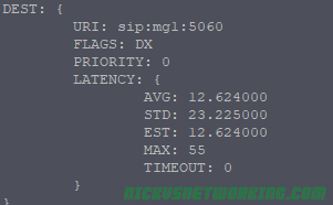
One question that’s not as obvious as it perhaps should be is the different states shown with kamcmd dispatcher.list command;
So what do the flags for state mean?
The first letter in the flag means is the current state, Active (A), Inactive (I) or Disabled (D).
The second letter in the flag means monitor status, Probing (P) meaning actively checked with SIP Options pings, or Not Set (X) denoting the device isn’t actively checked with SIP Options pings.
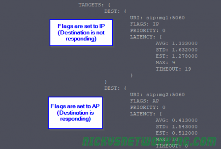
AP – Actively Probing – SIP OPTIONS are getting a response, routing to this destination is possible, and it’s “Up” for all intents and purposes.
IP – Inactively Probing – Destination is not meeting the threshold of SIP OPTIONS request responses it needs to be considered active. The destination is either down or not responding to all SIP OPTIONS pings. Often this is due to needing X number of positive responses before considering the destination as “Up”.
DX – Disabled & Not Probing – This device is disabled, no SIP OPTIONS are sent.
AX – Active & Not Probing– No SIP OPTIONS are sent to check state, but is is effectively “Up” even though the remote end may not be reachable.
In the third part of the Kamailio 101 series I briefly touched upon pseudovariables, but let’s look into what exactly they are and how we can manipulate them to change headers.
The term “pseudo-variable” is used for special tokens that can be given as parameters to different script functions and they will be replaced with a value before the execution of the function.
You’ve probably seen in any number of the previous Kamailio Bytes posts me use pseudovariables, often in xlog or in if statements, they’re generally short strings prefixed with a $ sign like $fU, $tU, $ua, etc.
When Kamailio gets a SIP message it explodes it into a pile of variables, getting the To URI and putting it into a psudovariable called $tU, etc.
We can update the value of say $tU and then forward the SIP message on, but the To URI will now use our updated value.
When it comes to rewriting caller ID, changing domains, manipulating specific headers etc, pseudovariables is where it mostly happens.
Kamailio allows us to read these variables and for most of them rewrite them – But there’s a catch. We can mess with the headers which could result in our traffic being considered invalid by the next SIP proxy / device in the chain, or we could mess with the routing headers like Route, Via, etc, and find that our responses never get where they need to go.
So be careful! Headers exist for a reason, some are informational for end users, others are functional so other SIP proxies and UACs can know what’s going on.
Rewriting SIP From Username Header (Caller ID)
When Kamailio’s SIP parser receives a SIP request/response it decodes the vast majority of the SIP headers into a variety of pseudovariables, we can then reference these variables we can then reference from our routing logic.
Let’s pause here and go back to the Stateless SIP Proxy Example, as we’ll build directly on that.
Follow the instructions in that post to get your stateless SIP proxy up and running, and we’ll make this simple change:
####### Routing Logic ########


/* Main SIP request routing logic
 * - processing of any incoming SIP request starts with this route
 * - note: this is the same as route { ... } */
request_route {

        xlog("Received $rm to $ru - Forwarding");
        $fU = "Nick Blog Example";   #Set From Username to this value
        #Forward to new IP
        forward("192.168.1.110");

}
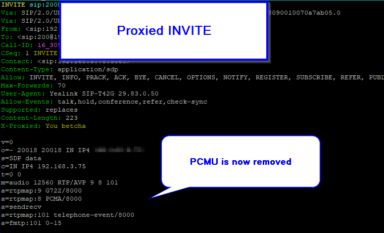
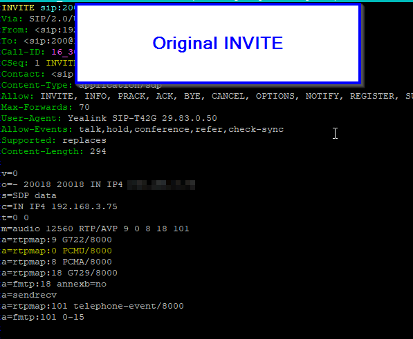
Now when our traffic is proxied the From Username will show “Nick Blog Example” instead of what it previously showed.
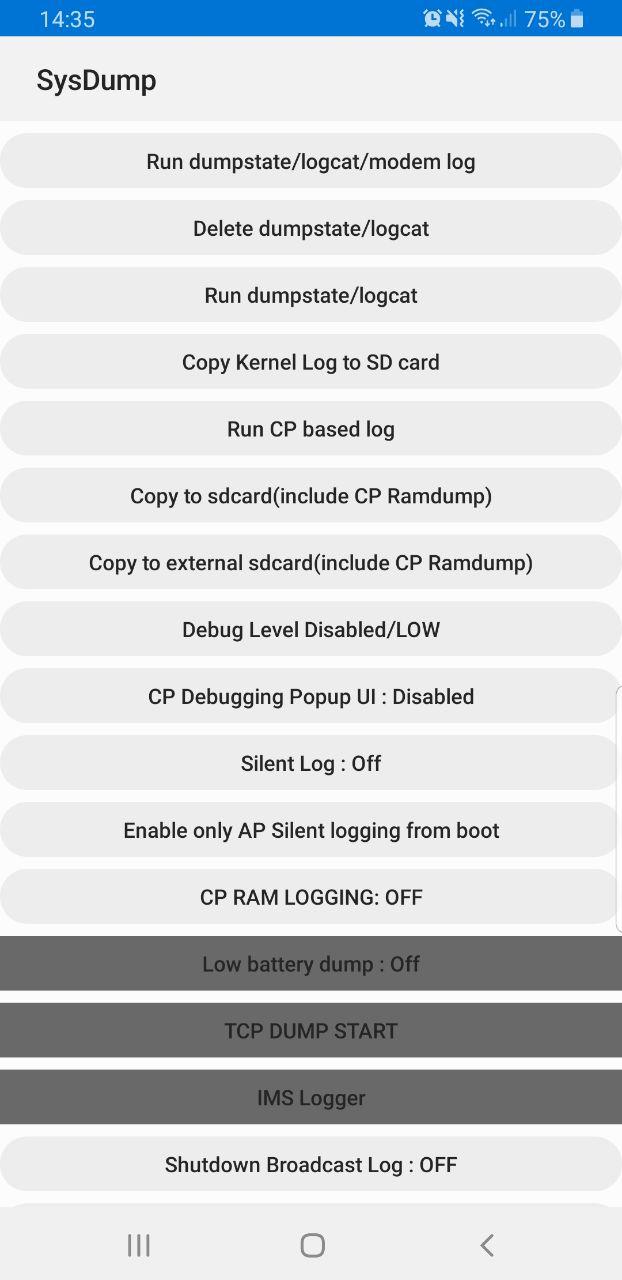
Samsung handsets have a feature built in to allow debugging from the handset, called Sysdump.
Entering *#9900# from the Dialing Screen will bring up the Sysdump App, from here you can dump logs from the device, and run a variety of debugging procedures.
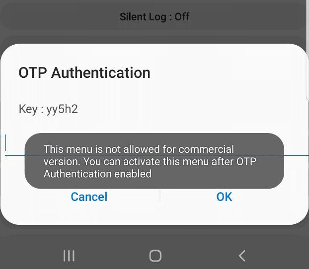
But for private LTE operators, the two most interesting options are by far the TCPDUMP START option and IMS Logger, but both are grayed out.
Tapping on them asks for a one-time password and has a challenge key.
These options are not available in the commercial version of the OS and need to be unlocked with a one time key generated by a tool Samsung for unlocking engineering firmware on handsets.
Luckily this authentication happens client side, which means we can work out the password it’s expecting.
Once you’ve entered the code and successfully unlocked the IMS Debugging tool there’s a few really cool features in the hamburger menu in the top right.
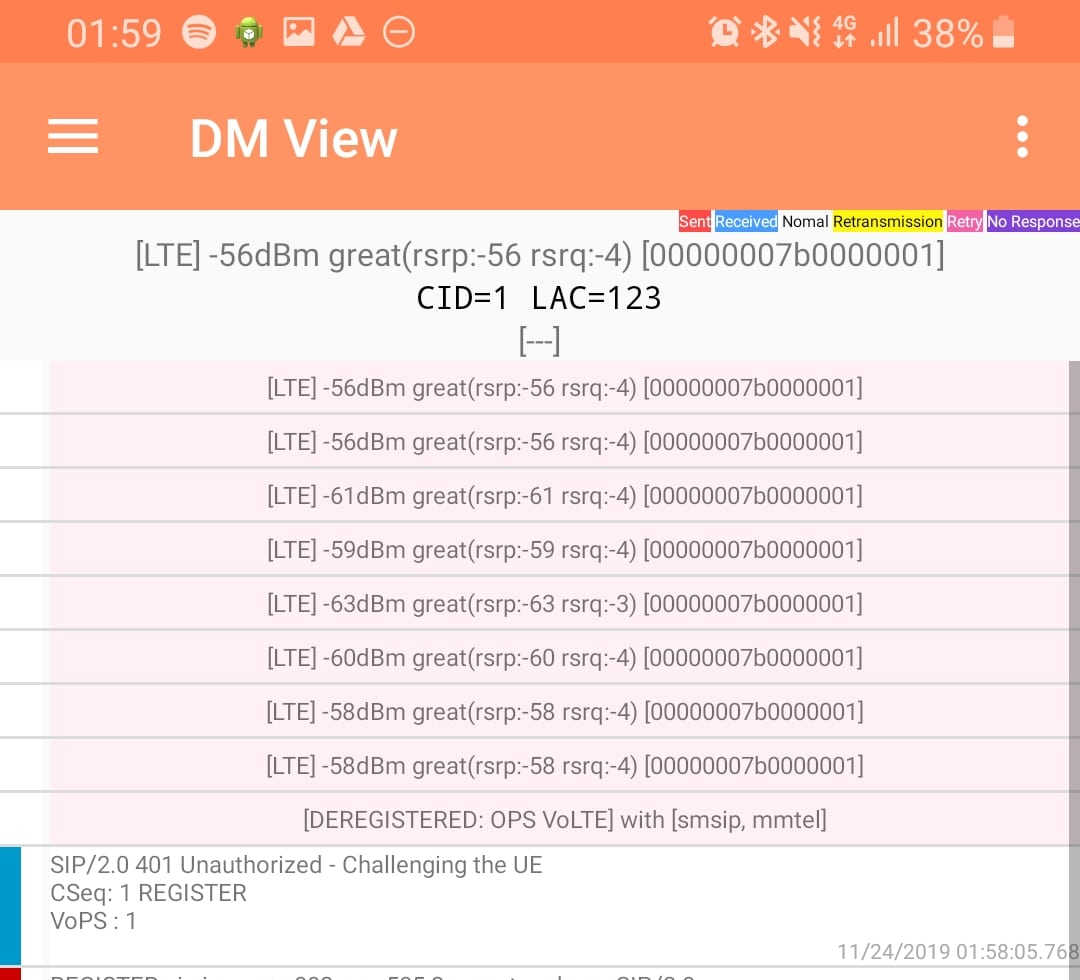
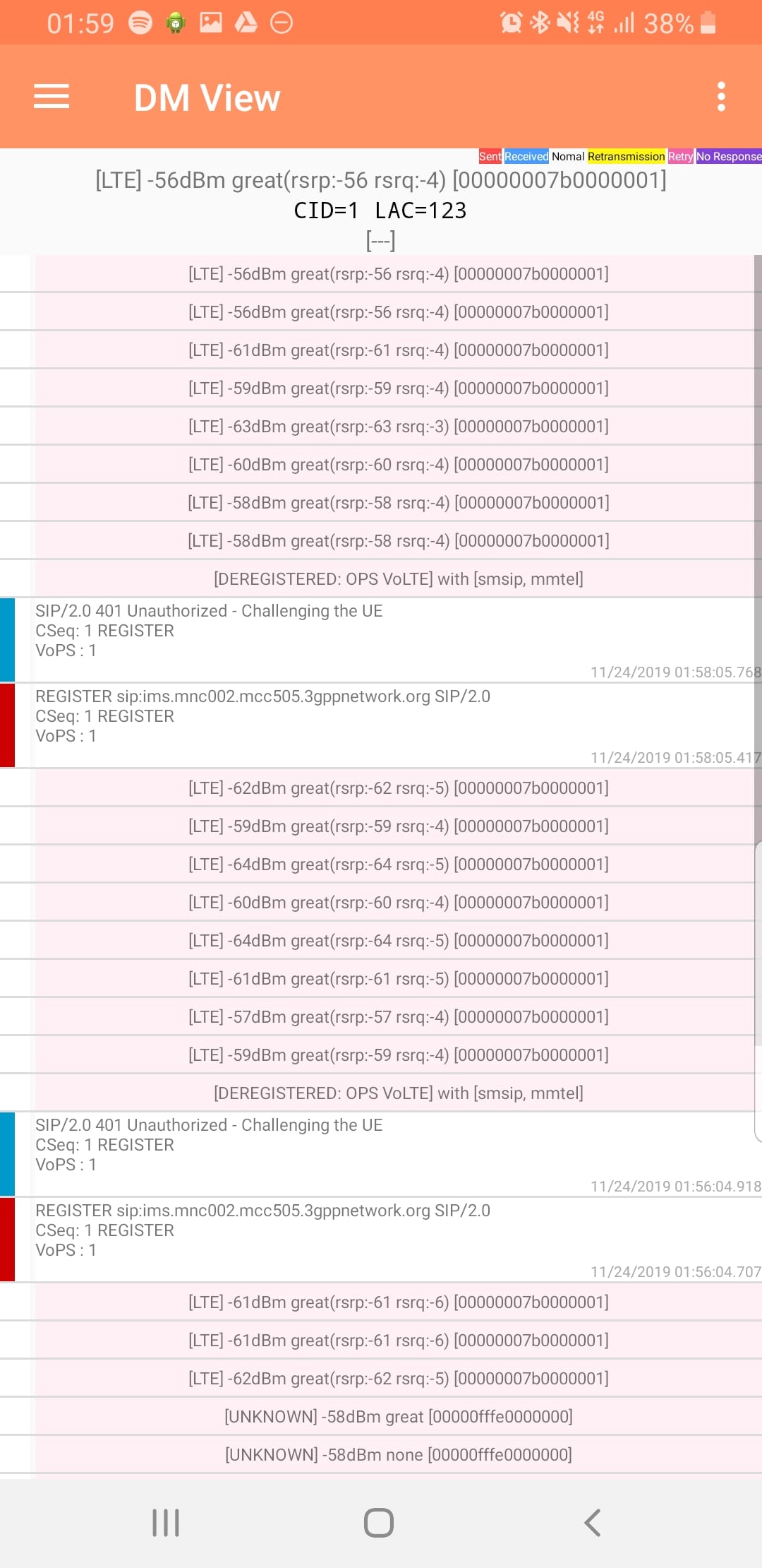
DM View
This shows the SIP / IMS Messaging and the current signal strength parameters (used to determine which RAN type to use (Ie falling back from VoLTE to UMTS / Circuit Switched when the LTE signal strength drops).
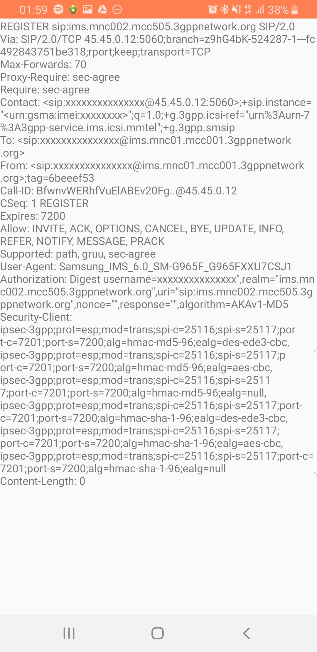
Tapping on the SIP messages expands them and allows you to see the contents of the SIP messages.
Viewing SIP Messaging directly from the handset
Interesting the actual nitty-gritty parameters in the SIP headers are missing, replaced with X for anything “private” or identifiable.
Luckily all this info can be found in the Pcap.
The DM View is great for getting a quick look at what’s going on, on the mobile device itself, without needing a PC.
Logging
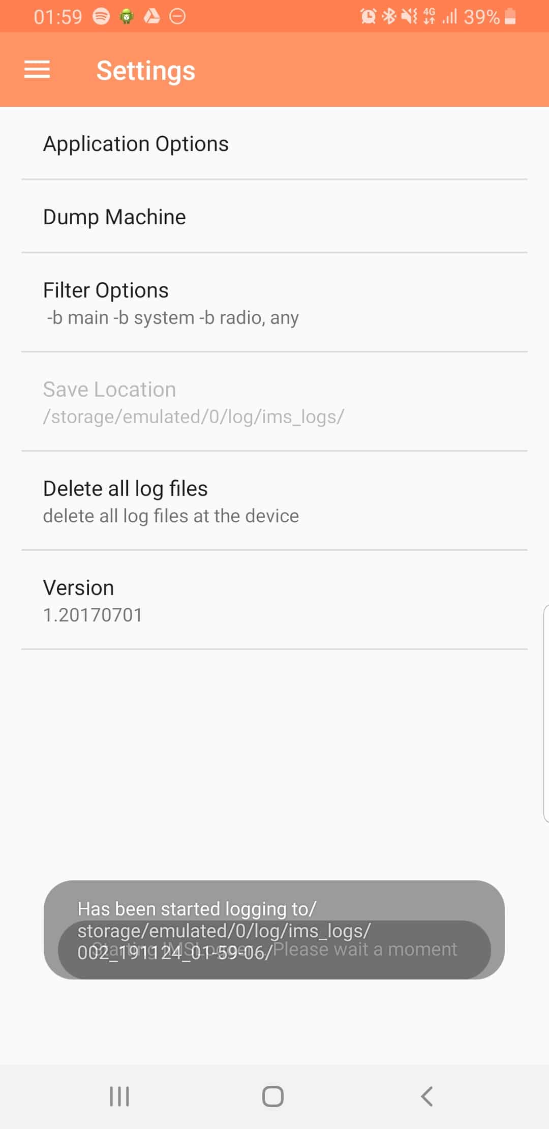
The real power comes in the logging functions,
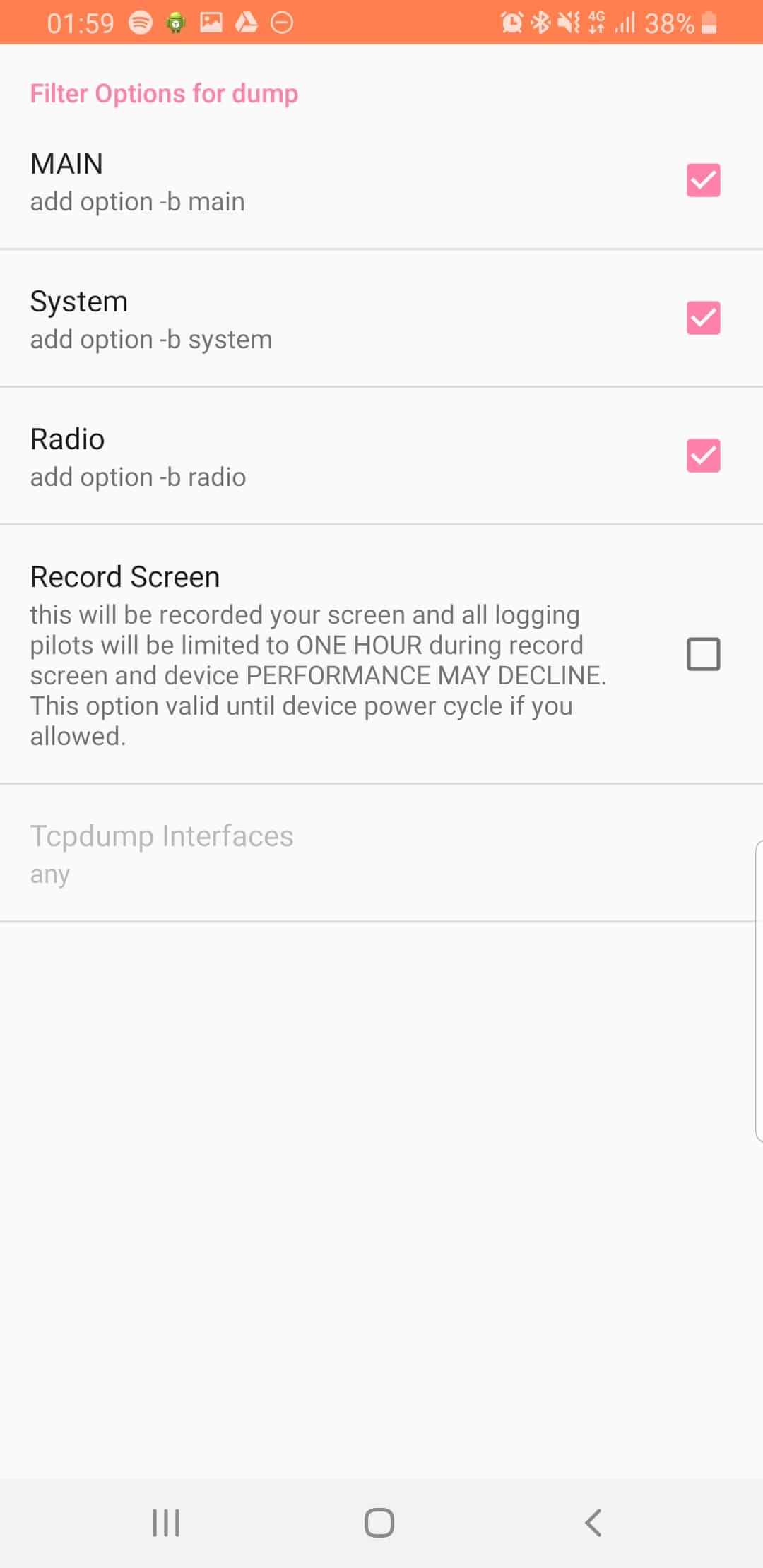
There’s a lot of logging options, including screen recording, TCPdump (as in Packet Captures) and Syslog logging.
From the hamburger menu we can select the logging parameters we want to change.
From the Filter Options menu we can set what info we’re going to log,
The Australian telecommunications industry was deregulated in 1997, meaning customers could have telecommunications services through a Carriage Service Provider (CSP) of their choice.
In order to increase competition and make it easier to move to a different CSP, the ACMA (Or as they were then the ACA) declared that Local Numbers (Geo numbers / land lines) were a “Portable Service”. This meant that if a customer didn’t like their current Carriage Service Provider (CSP) they could give them the flick (making them the Loosing Carrier), move to a new CSP (Gaining Carrier) but keep their existing phone numbers by moving them to the new carrier in a process known as Local Number Portability (LNP).
The Local Number Portability (LNP) standard was first defined by Comms Alliance in 1999 in ACIF C540 and defines the process of moving numbers between Carriage Service Providers (CSPs), however 22 years later the process can still be a baffling system for many customers, end users and carrier staff to navigate.
Acronyms galore exist and often the porting teams involved themselves aren’t 100% sure what goes on in the porting process.
In 1997 ISDN was first still an emerging technology and porting was typically a customer moving from one PSTN / POTS line provided by one CSP to another PSTN / POTS line provided by a different CSP – a simple port.
Two processes were defined, one for managing simple ports involving moving one simple number from one CSP to another CSP – Called Simple Porting or “Cat A” – which made up the majority of porting requests at the time, and another process for everything else managed by a project manager from the Loosing and Gaining CSP called Complex Porting or “Cat C“.
Simple porting, classified as “Cat A” is used for porting single simple services (numbers).
The Cat A process can only be used for moving a “simple” standalone number – with no additional features – from one carrier to another.
The typical use case for Cat A port is moving a one copper PSTN / POTS line (Active line with no Fax Duet, Line Hunt, etc) from one carrier to another – as I said before, Cat A ports made up the majority of porting requests when the system was first introduced as the vast majority of services were copper POTS lines.
The process is automated at both ends, essentially the carriers send each other the numbers to be moved (more on that later) and their switches automatically process this and begin routing the number.
These ports are typically completed within a few days to a week and the customer gets a notification when the port is completed.
Cat C / Complex Number Porting
For all number porting that don’t meet the very specific requirements of Cat A aren’t met – and sometimes even if they are met, ports are processed as Cat C ports.
Cat C ports require a project manager at both the Gaining Carrier and the Losing Carrier to agree on the details for the port and the move the numbers, each using their own internal process.
Lead times on Cat C ports are long – and getting longer, so from submitting a port to it’s completion can take 90+ days, and there is no confirmation required to the customer to let them know the services have been ported successfully.
Administrative Process of Ports (CatA & CatC)
Strap yourself in for a whirlwind of acronyms…
The Code does not constrain two or more individual industry participants agreeing to different arrangements
Section 1.3.6
Because of this it means this is the minimum standard, some CSPs have improved upon this between each other, however there’s a bit of a catch 22 in that CSPs have no incentive to make porting numbers out easier, as they’re typically losing that customer, so the process is typically not improved upon in any meaningful way that makes the customer experience easier.
Without further ado, here’s what Cat A & Cat C ports look like under the hood…
Note: These all assume the Losing CSP is also the Donor CSP. More on that in the LNP FAQ and Call Routing posts.
Cat A – Simple Porting – Process
Summary
Cat A ports are automated – The process involves CSPs transferring formatted data between each other and the process that goes on for these ports.
The Losing CSP must use the Cat A process if the service meets the requirements to be ported under a Cat A and the Gaining Carrier has submitted it as a Cat A port. This means a Cat A port can’t be rejected by the losing carrier as not a valid Cat A port to be resubmitted as a Cat C port, if it does actually meet the requirements for Cat A porting. That said numbers that are valid in terms of Cat A can be submitted as a Cat C, this is often cheaper than submitting multiple Cat A porting requests when you have more than 5 or so services to be ported.
Here’s a brief summary of the process:
Customer requests port and details are validated
Simple Notification Advice (SNA) is sent to the Losing CSP via a Porting Notification Order (PNO) – Essentially a form send to the losing CSP of the intention to port the service
Losing CSP sends back SNA Confirmation Advice to confirm the service can be ported
Electronic Cutover Advice (ECA) sent by gaining CSP to indicate gaining CSP wanting to initiate port
Losing CSP provides Donor Routing by essentially redirecting calls to the Gaining CSP
ECA Confirmation Advice sent by losing CSP to denote the service has been removed from the losing CSP’s network & number is with gaining CSP as far as they are concerned
Losing CSP updates a big text file (PLNR) with a list of numbers allocated to it, to show the numbers have been ported to a different carrier and indicates which carrier
We’ll talk about the technical process of how the data is transferred, what PLNR is and how routing is managed, later on.
In depth process:
Step 1 – Customer Authority
The Gaining CSP must obtain Customer’s Authority (CA) to port number (Section 4.1.2) – Typically this takes the form of a number porting form filled in by the customer, containing a list of numbers to port, account numbers with losing carrier and date.
If requested by the customer the Losing CSP must explain any costs / termination payments / contractual obligations to the customer (Section 4.1.4), however the Losing CSP cannot reject the port based upon an outstanding contract being in place.
Step 2 – Validation
Before anything technical happens, the Gaining CSP must validate the porting request is valid – this means verifying:
The requested numbers are able to be ported under the selected method (Cat A or Cat C)
Confirming the date of the Customer Authority is less than 90 days old
The requested numbers must be recorded
In practice these 3 steps are typically handled by a single form filled out by the customer in the first step. (Section 4.1.5)
If requested by the Losing CSP this Customer Authority information has to be given to the Losing CSP. This typically happens in cases of disputed ownership / management of a number.
Step 3 – The SNA PNO
Once the Gaining CSP is satisfied the port is valid, a Simple Notification Advice (SNA) is sent to the Losing CSP via a Porting Notification Order (PNO) (Section 4.2.2).
The PNO is essentially a form that includes:
Area Code & Telephone Number of service to be ported
Service Account number with Losing CSP
Porting Category set to Cat A
Date of Customer Authority
The Losing CSP must then validate this info, by checking: (Section 4.2.4)
The requested number is a Simple service (Meets the requirements of Cat A)
Is with the Losing CSP (Has not been ported to another carrier already)
Is not disconnected or pending disconnection at the time the SNA was submitted
The Customer Authority (CA) date is not more than 90 days old
Does not currently have a port request pending
After the Losing CSP has gone through this they will send back a SNA Confirmation Advice if the port request (SNA PNO) is valid or a SNA Reject Advice along with the phone number and reason for rejection if the port request is deemed invalid.
The confirmation, if SNA Confirmation Advice is received, is deemed valid for 30 days, after which the process would have to start again and the SNA PNO would have to be regenerated.
Step 4 – Electronic Cutover Advice (ECA)
After the Losing CSP sends back a SNA Confirmation Advice, the gaining carrier sends the Losing Carrier an Electronic Cutover Advice (ECA) via the Final Cutover Notification Interface (Section 4.2.24 ).
When the Losing CSP get the ECA it’s showtime. The Losing CSP checks that there’s a valid SNAin place for the number to be ported and that it’s less than 2 days old (Section 4.2.27).
If the Losing CSP is not satisfied they send back a ECA Reject Advice listing the reason for rejection within 15 minutes (Section 4.2.32).
If all looks good, the Losing Carrier sends the Gaining CSP back a ECA Confirmation Advice within 15 minutes (Section 4.2.33).
Now is when the magic happens – the Losing CSP “ports out” that number via their internal process, for this they provide temporary Donor Transit Routing – Essentially redirecting any calls that come into the ported number to the new carrier.
Finally the Losing CSP sends a Electronic Completion Advice (ECA) to confirm they’ve processed the port out from their network (Section 4.2.34).
Within a day of the port completing, the Losing CSP updates the Ported Local Number Registry (PLNR) to show the service has been ported out and the identifier of the gaining carrier the number has been ported to. PLNR is nothing more than a giant text file containing a list of all the numbers originally allocated to the Losing CSP and the carrier code they should now be routing to, this data is published so the other CSPs can read it.
Other CSPs read this PLNR data and update their routing tables, meaning the calls will route directly to the new Gaining CSP, and the Donor Routing can be removed on the Losing CSPs switch.
Cat C – Complex Porting – Process
Summary
Cat C ports are a manually project managed, and unlike Cat A are not automated.
This means that the Losing and Gaining CSP must both allocate a “project manager”, the two to liaise with each other (typically via email) to confirm the numbers can be ported and then find a suitable time to port the numbers, finally at the agreed upon date & time each side kicks off their own process to move the numbers and confirm when it’s done.
Porting Number Validation – PNV
Before a Cat C port can be initiated the PNV process is typically called upon to validate the port won’t get rejected. This isn’t mandatory but is often used as PNV is processed relatively quickly which means any issues with the services can be worked out prior to submitting the port request.
The submitted PNV request is very similar to the actual Cat C porting request (CNA), containing the customer’s details and list of services to be ported.
The losing CSP returns the list of numbers each with a response code denoting particulars of the service, and if rejected, a rejection code.
Response Codes:
Reason Code
Reason
P
Prime/Directory Service Number
A
Associated Service Numbers
S
Standalone Number
R
Reserved Number
D
Exchange based diversion
SS
Secondary Service linked to this Number (e.g. DSL)
Reject Codes:
Code
Reason
1
Invalid Customer Authorization date
Whole Request
2
Insufficient information supplied
Whole Request
3
Telephone Number appears to belong to a completely different end customer
Per Number
4
Telephone Numbers relate to cancelled services or services pending cancellation
Per Number
5
Missing / invalid PNV Sequence Number
Per Number
6
Telephone Numbers in the PNV request relate to services which are billed by a service provider other than the Losing Carrier.
Per Number
7
Telephone Numbers are not found / not present on Losing Carrier’s Network
Per Number
(Section 4.3.8)
It’s worth noting the main reason PNV is used so heavily in Cat C ports is if a batch of numbers / services are requested to be ported in a single Cat C porting request, if any one of those numbers gets rejected the whole port will need to be resubmitted, hence it being important that before submitting the numbers to be ported, the Gaining CSP verifies they can be ported via the PNV process.
The PNV does not guarantee a physical audit of the services, but rather an audit of available electronic data by the losing CSP. It’s also only valid for the day of issue, so services can change between a PNV coming back clear and the port request being rejected.
99% of PNV requests should be processed within 5 business days. (Section 4.3.9)
Step 1 – Complex Notification Advice (CNA)
To initiate the port the gaining CSP submits a Complex Notification Advice(CNA) to the losing CSP.
This contains all the data you’d expect, including customer’s details and the list of services/numbers to be ported, along with a batch number that’s unique to the Gaining CSP (Like a ticket / request number) and Gaining CSP’s Project Manager – The staff member as the Gaining CSP that will be responsible for the port.
Upon receipt, the Losing CSP sends back a CNA Receipt Advice to confirm they’ve received and begins validating the CNA in a process very similar to the PNV process. (Section 4.4.1)
Step 2 – CNA Confirmation Advice
If verification fails and the CNA request is deemed not valid the CNA is rejected by the Losing CSP, who sends back a CNA Reject Advice response. This response will contain a list of services and the reject code for each rejected service as per the PNV process.
If the CNA is deemed valid, the Losing CSP responds with a CNA Confirmation Advice message, containing the Losing CSP’s project manager for this port, along with the Gaining CSP’s batch number to the Gaining CSP.
This is sent in a batch file along with other CNA Confirmation Advice messages within 5 days. (Section 4.4.6)
Step 3 – Complex Cutover Advice (CCA)
Once the Gaining CSP has the CNA Confirmation Advice the project manager for the port at the Gaining CSP contacts the nominated project manager at the Losing CSP and the two have to agree on a cutover date and time for the port. (Section 4.4.8)
The agreed date and time of the port is sent by the Gaining CSP to the Losing CSP in the from of a Complex Cutover Advice (CCA) containing the Gaining CSP batch number and agreed date & time. (Section 4.4.27)
If the details of the CCA are valid from the Losing CSP’s perspective, the Losing CSP sends back CCA Confirmation Advice to confirm receipt.
Step 4 – The Porting
At the agreed upon date & time both CSPs are to execute the port from their organization’s perspective.
Typically the losing CSP provides Donor Transit Routing forwarding / redirecting calls to the ported out number to the new CSP.
There is no completion advice and no verification the port has been completed successfully required by the code. (Section 4.4.48)
Within a day of the port completing, the Losing CSP updates the Ported Local Number Registry (PLNR).
Other CSPs read this PLNR data and update their routing tables, meaning the calls will route directly to the new Gaining CSP, and the Donor Routing can be removed on the Losing CSPs switch.
On a PCM (G.711) RTP packet the payload is typically 160 bytes per packet.
But the total size of the frame on the wire is typically ~214 bytes, to carry a 160 byte payload that means 25% of the data being carried is headers.
This is fine for VoIP services operating over fixed lines, but when we’re talking about VoLTE / IMS and the traffic is being transferred over Radio Access Networks with limited bandwidth / resources, it’s important to minimize this as much as possible.
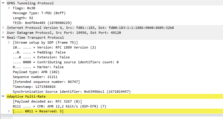
IMS uses the AMR codec, where the RTP payload for each packet is around 90 bytes, meaning up to two thirds of the packet on the wire (Or in this case the air / Uu interface) is headers.
Using ROHC the size of the headers are cut down to only 4-5 bytes, this is because the IPv4 headers, UDP headers and RTP headers are typically the same in each packet – with only the RTP Sequence number, RTP timestamp IPv4 & UDP checksum and changing between frames.
I modified the Kamailio config allow Transcoding, as I talked about in the post on setting up Transcoding in RTPengine with Kamailio.
Now I had a working Kamailio instance with RTPengine that was transcoding.
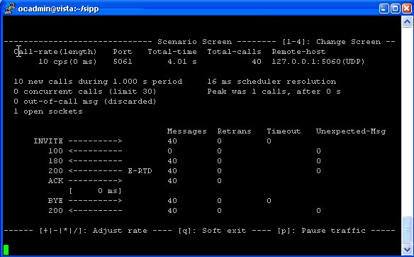
So the next step becomes testing the transcoding is working, for this I had two SIPp instances, one to make the calls and once to answer them.
Instance 1
Makes calls to the IP of the Kamailio / RTPengine instance, for this I modified the uac_pcap scenario to playback an RTP stream of a PCMA (G.711 a-law) call to the called party (stored in a pcap file), and made it call the Kamailio instance multiple times based on how many concurrent transcoding sessions I wanted:
We’ve talked about using a few different modules, like a SIP Registrar and Htable, that rely on data stored in Kamailio’s memory, the same is true for all the Stateful proxy discussion last week.
But what if you want to share this data between multiple Kamailio instances? This allows distributing workload and every server having the same information and therefore any server is able to process any request.
This allows memory data to be shared between multiple Kamailio instances (aka “Nodes”), so for example if you are storing data in Htable on one Kamailio box, all the other boxes/nodes in the DMQ pool will have the same HTable data.
Kamailio uses SIP to transfer DMQ messages between DMQ nodes, and DNS to discover DMQ nodes.
For this example we’ll share user location data (usrloc) between Kamailio instances, so we’ll create a very simple setup to store location data:
####### Routing Logic ########


/* Main SIP request routing logic
 * - processing of any incoming SIP request starts with this route
 * - note: this is the same as route { ... } */
request_route {

        #Enable record_routing so we see the BYE / Re-INVITE etc

        if(is_method("REGISTER")){

                save("location");
        }else{
                sl_reply("500", "Nope");
        }


}
Now if we register a SIP endpoint we should be able to view it using Kamcmd’s ul.dump call, as we talked about in the Kamailio SIP Registrar tutorial.
Next we’ll setup DMQ to allow this data to be shared to other nodes, so they also have the same userloc data available,
First we’ll begin by binding to an extra port for the DMQ messages to go to, to make it a bit clearer what is normal SIP and what’s DMQ,
So for this we’ll add a new line in the config to listen on port 5090:
/* uncomment and configure the following line if you want Kamailio to
 * bind on a specific interface/port/proto (default bind on all available) */
listen=udp:0.0.0.0:5060
listen=tcp:0.0.0.0:5060
listen=udp:0.0.0.0:5090
The server_address means we’re listening on any IP on port 5090. In production you may have an IP set here of a private NIC or something non public facing.
The notification address resolves to 2x A records, one is the IP of this Kamailio instance / node, the other is the IP of the other Kamailio instance / node, I’ve just done this in /etc/hosts
Finally we’ll add some routing logic to handle the DMQ messages coming in on port 5090:
####### Routing Logic ########


/* Main SIP request routing logic
 * - processing of any incoming SIP request starts with this route
 * - note: this is the same as route { ... } */
request_route {


        if (is_method("KDMQ") && $Rp == 5090)
        {
                dmq_handle_message();
        }

        #Enable record_routing so we see the BYE / Re-INVITE etc

        if(is_method("REGISTER")){

                save("location");
        }else{
                sl_reply("500", "Nope");
        }


}
We’ll put the same config on the other Kamailio instance and restart Kamailio on both.
We can now check the DMQ node status to confirm they’re talking to each other.
We talked a little about the Transaction module and using it for Transaction Stateful SIP Proxy, but it’s worth knowing a bit more about the Transaction Module and the powerful functions it offers.
So today I’ll cover some cool functionality TM offers!
Different Reply Routes
By calling the t_on_reply(); we can specify the reply route to be used for replies in this transaction.
route[RELAY]{

        #Use reply route "OurReplyRoute" for responses for this transaction
        t_on_reply("OurReplyRoute");

        #Relay (aka Forward) the request
        t_relay_to_udp("192.168.3.118", "5060");

}

onreply_route[OurReplyRoute] {
        #On replies from route[RELAY]

        #Check our AVP we set in the initial request
        xlog("for $rs response the value of AVP \"state_test_var\" is $avp(state_test_var) ");

        #Append a header so we can see this was proxied in the SIP capture
        append_hf("X-Proxied: For the reply\r\n");

}
Any responses from the route[RELAY] routing block will go to onreply_route[OurReplyRoute], the beauty of this is it allows you to have multiple reply routes each with their own logic. For example for a call leg to a carrier you may want to preserve CLI, but for a call leg to a customer you may wish to restrict it if that’s the option the user has selected, and you can make these changes / modifications in the reply messages.
Failure Routes
Failure routes allow the transaction module to know to try again if a call fails, for example if no response is received from the destination, send it to a different destination, like a backup.
route[RELAY]{

        #Use reply route "OurReplyRoute" for responses for this transaction
        t_on_reply("OurReplyRoute");
        t_on_failure("OurFailureRoute");
        #Relay (aka Forward) the request
        t_relay_to_udp("192.168.1.118", "5060");

}

failure_route[OurFailureRoute]{
        xlog("At failure route");
        t_reply("500", "Remote end never got back to us");
        exit;
}
We can build upon this, and try a different destination if the first one fails:
request_route {

        #Enable record_routing so we see the BYE / Re-INVITE etc
        record_route();

        #Handle Registrations in a dumb way so they don't messy our tests
        if(is_method("REGISTER")){
                sl_reply("200", "ok");
                exit;
        }


                 #Append a header so we can see this was proxied in the SIP capture
                append_hf("X-Proxied: You betcha\r\n");

        if(is_method("INVITE")){
                        #Createa  new AVP called "state_test_var" and set the value to "I remember"
                        $avp(state_test_var) = "I remember";
        }
                #Let syslog know we've set the value and check it
                xlog("for $rm the value of AVP \"state_test_var\" is $avp(state_test_var) ");

                #Send to route[RELAY] routing block
                rewritehostport("nonexistentdomain.com");
                route(RELAY);

}

route[RELAY]{

        #Use reply route "OurReplyRoute" for responses for this transaction
        t_on_reply("OurReplyRoute");
        t_on_failure("OurFailureRoute");
        #Relay (aka Forward) the request
        t_relay();
}

failure_route[OurFailureRoute]{
        xlog("At failure route");
        #t_reply("500", "Remote end never got back to us");

                rewritehostport("192.168.3.118");
                append_branch();
                t_relay();

}

onreply_route[OurReplyRoute] {
        #On replies from route[RELAY]

        #Check our AVP we set in the initial request
        xlog("for $rs response the value of AVP \"state_test_var\" is $avp(state_test_var) ");

        #Append a header so we can see this was proxied in the SIP capture
        append_hf("X-Proxied: For the reply\r\n");

}
One thing to keep in mind is that there’s lots of definitions of failure, for example if you are sending a call to a carrier and get a 404 response back, you probably want to relay that through to the end user, because that destination isn’t there.
But if you get back a 5xx series response you may consider that to be a failure and select the next carrier for example.
Different conditions / requirements have different definitions of “failures” and so there’s a lot to think about when implementing this, along with timeouts for no replies, TCP session management, etc.
Parallel Forking the Call to Multiple Destinations
Parallel Forking is a fancy way of saying ring multiple destinations at the same time.
/* Main SIP request routing logic
 * - processing of any incoming SIP request starts with this route
 * - note: this is the same as route { ... } */
request_route {

        #Enable record_routing so we see the BYE / Re-INVITE etc
        record_route();

        #Handle Registrations in a dumb way so they don't messy our tests
        if(is_method("REGISTER")){
                sl_reply("200", "ok");
                exit;
        }


                 #Append a header so we can see this was proxied in the SIP capture
                append_hf("X-Proxied: You betcha\r\n");

        if(is_method("INVITE")){
                        #Createa  new AVP called "state_test_var" and set the value to "I remember"
                        $avp(state_test_var) = "I remember";
        }
                #Let syslog know we've set the value and check it
                xlog("for $rm the value of AVP \"state_test_var\" is $avp(state_test_var) ");

                #Send to route[RELAY] routing block
                route(RELAY);

}

route[RELAY]{

        #Use reply route "OurReplyRoute" for responses for this transaction
        t_on_reply("OurReplyRoute");

        #Append branches for each destination we want to forward to
        append_branch("sip:[email protected]");
        append_branch("sip:[email protected]");
        append_branch("sip:[email protected]");

        t_on_failure("OurFailureRoute");
        #Relay (aka Forward) the request
        t_relay();
}

failure_route[OurFailureRoute]{
        xlog("At failure route");
        t_reply("500", "All those destinations failed us");

}

onreply_route[OurReplyRoute] {
        #On replies from route[RELAY]

        #Check our AVP we set in the initial request
        xlog("for $rs response the value of AVP \"state_test_var\" is $avp(state_test_var) ");

        #Append a header so we can see this was proxied in the SIP capture
        append_hf("X-Proxied: For the reply\r\n");

}
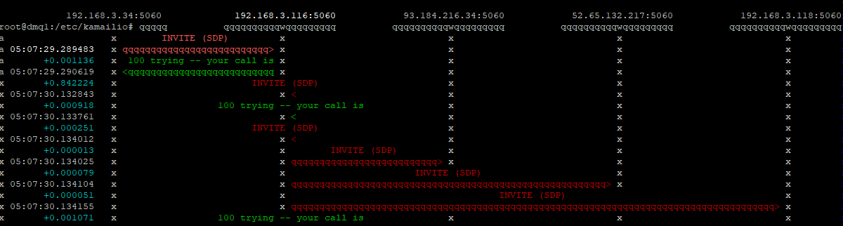
Bit of a mess but here we see the initial INVITE being branched to the 3 destinations at the same time (Parallel forking)
Serial Forking / Sequential Forking the calls to Multiple Destinations one after the Other
This could be used to try a series of weighted destinations and only try the next if the preceding one fails:
/* Main SIP request routing logic
 * - processing of any incoming SIP request starts with this route
 * - note: this is the same as route { ... } */
request_route {

        #Enable record_routing so we see the BYE / Re-INVITE etc
        record_route();


        #Send to route[RELAY] routing block
        route(RELAY);

}

route[RELAY]{

        #Use reply route "OurReplyRoute" for responses for this transaction
        t_on_reply("OurReplyRoute");

        append_branch("sip:[email protected]", "0.3");
        append_branch("sip:[email protected]", "0.2");
        append_branch("sip:[email protected]", "0.1");

        t_load_contacts();

        t_next_contacts();

        t_on_failure("OurFailureRoute");
        #Relay (aka Forward) the request
        t_relay();
        break;
}

failure_route[OurFailureRoute]{

        xlog("At failure route - Trying next destination");
        t_on_failure("OurFailureRoute");
        t_relay();


}

onreply_route[OurReplyRoute] {
        #On replies from route[RELAY]
        #Append a header so we can see this was proxied in the SIP capture
        append_hf("X-Proxied: For the reply\r\n");

}
Again this will try each destination, but one after the other based on the weight we added to each destination in the append_branch()
Here we see each destination being tried sequentially
The 3 different proxies all do the same thing, they all relay SIP messages, so we need a way to determine what state has been saved.
To do this we’ll create a variable (actually an AVP) in the initial request (in our example it’ll be an INVITE), and we’ll reference it when handling a response to make sure we’ve got transactional state.
We’ll also try and reference it in the BYE message, which will fail, as we’re only creating a Transaction Stateful proxy, and the BYE isn’t part of the transaction, but in order to see the BYE we’ll need to enable Record Routing.
Stateless Proof
Before we add any state, let’s create a working stateless proxy, and add see how it doesn’t remember:
####### Routing Logic ########


/* Main SIP request routing logic
 * - processing of any incoming SIP request starts with this route
 * - note: this is the same as route { ... } */
request_route {

        #Enable record_routing so we see the BYE / Re-INVITE etc
        record_route();

        #Handle Registrations in a dumb way so they don't messy our tests
        if(is_method("REGISTER")){
                sl_reply("200", "ok");
                exit;
        }


                 #Append a header so we can see this was proxied in the SIP capture
                append_hf("X-Proxied: You betcha\r\n");

        if(is_method("INVITE")){
                        #Createa  new AVP called "state_test_var" and set the value to "I remember"
                        $avp(state_test_var) = "I remember";
        }
                #Let syslog know we've set the value and check it
                xlog("for $rm the value of AVP \"state_test_var\" is $avp(state_test_var) ");

                #Forard to new IP
                forward("192.168.3.118");


}

onreply_route{
        #Check our AVP we set in the initial request
        xlog("for $rs response the value of AVP \"state_test_var\" is $avp(state_test_var) ");

        #Append a header so we can see this was proxied in the SIP capture
        append_hf("X-Proxied: For the reply\r\n");
}
Now when we run this and call from any phone other than 192.168.3.118, the SIP INVITE will hit the Proxy, and be forwarded to 192.168.3.118.
Syslog will show the INVITE and us setting the var, but for the replies, the value of AVP $avp(state_test_var) won’t be set, as it’s stateless.
Let’s take a look:
kamailio[2577]: {1 1 INVITE [email protected]} ERROR: : for INVITE the value of AVP "state_test_var" is I remember
kamailio[2575]: {2 1 INVITE [email protected]} ERROR: <script>: for 100 response the value of AVP "state_test_var" is <null>
kamailio[2576]: {2 1 INVITE [email protected]} ERROR: <script>: for 180 response the value of AVP "state_test_var" is <null>
kamailio[2579]: {2 1 INVITE [email protected]} ERROR: <script>: for 200 response the value of AVP "state_test_var" is <null>
kamailio[2580]: {1 1 ACK [email protected]} ERROR: <script>: for ACK the value of AVP "state_test_var" is <null>
kamailio[2581]: {1 2 BYE [email protected]} ERROR: <script>: for BYE the value of AVP "state_test_var" is <null>
We can see after the initial INVITE none of the subsequent replies knew the value of our $avp(state_test_var), so we know the proxy is at this stage – Stateless.
Doing the heavy lifting of our state management is the Transaction Module (aka TM). The Transaction Module deserves a post of it’s own (and it’ll get one).
We’ll load the TM module (loadmodule “tm.so”) and use thet_relay() function instead of the forward() function.
But we’ll need to do a bit of setup around this, we’ll need to create a new route block to call t_relay() from (It’s finicky as to where it can be called from), and we’ll need to create a new reply_route{} to manage the response for this particular dialog.
Let’s take a look at the code:
####### Routing Logic ########


/* Main SIP request routing logic
 * - processing of any incoming SIP request starts with this route
 * - note: this is the same as route { ... } */
request_route {

        #Enable record_routing so we see the BYE / Re-INVITE etc
        record_route();

        #Handle Registrations in a dumb way so they don't messy our tests
        if(is_method("REGISTER")){
                sl_reply("200", "ok");
                exit;
        }


                 #Append a header so we can see this was proxied in the SIP capture
                append_hf("X-Proxied: You betcha\r\n");

        if(is_method("INVITE")){
                        #Createa  new AVP called "state_test_var" and set the value to "I remember"
                        $avp(state_test_var) = "I remember";
        }
                #Let syslog know we've set the value and check it
                xlog("for $rm the value of AVP \"state_test_var\" is $avp(state_test_var) ");

                #Send to route[RELAY] routing block
                route(RELAY);

}

route[RELAY]{

        #Use reply route "OurReplyRoute" for responses for this transaction
        t_on_reply("OurReplyRoute");

        #Relay (aka Forward) the request
        t_relay_to_udp("192.168.3.118", "5060");

}

onreply_route[OurReplyRoute] {
        #On replies from route[RELAY]

        #Check our AVP we set in the initial request
        xlog("for $rs response the value of AVP \"state_test_var\" is $avp(state_test_var) ");

        #Append a header so we can see this was proxied in the SIP capture
        append_hf("X-Proxied: For the reply\r\n");

}
So unlike before where we just called forward(); to forward the traffic we’re now calling in a routing block called RELAY.
Inside route[RELAY] we set the routing block that will be used to manage replies for this particular transaction, and then call t_relay_to_udp() to relay the request.
We renamed our onreply_route to onreply_route[OurReplyRoute], as specified in the route[RELAY].
So now let’s make a call (INVITE) and see how it looks in the log:
kamailio[5008]: {1 1 INVITE [email protected]} ERROR: : for INVITE the value of AVP "state_test_var" is I remember
kamailio[5005]: {2 1 INVITE [email protected]} ERROR: <script>: for 100 response the value of AVP "state_test_var" is I remember
kamailio[5009]: {2 1 INVITE [email protected]} ERROR: <script>: for 180 response the value of AVP "state_test_var" is I remember
kamailio[5011]: {2 1 INVITE [email protected]} ERROR: <script>: for 200 response the value of AVP "state_test_var" is I remember
kamailio[5010]: {1 1 ACK [email protected]} ERROR: <script>: for ACK the value of AVP "state_test_var" is <null>
kamailio[5004]: {1 2 BYE [email protected]} ERROR: <script>: for BYE the value of AVP "state_test_var" is <null>
kamailio[5007]: {2 2 BYE [email protected]} ERROR: <script>: for 200 response the value of AVP "state_test_var" is <null>
Here we can see for the INVITE, the 100 TRYING, 180 RINGING and 200 OK responses, state was maintained as the variable we set in the INVITE we were able to reference again.
(The subsequent BYE didn’t get state maintained because it’s not part of the transaction.)
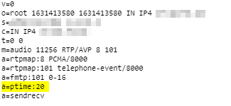
ptime is the packetization timer in VoIP, it’s set in the SDP message and defines the length of each RTP packet that’s sent;
This gives the length of time in milliseconds represented by the media in a packet. This is probably only meaningful for audio data, but may be used with other media types if it makes sense. It should not be necessary to know ptime to decode RTP or vat audio, and it is intended as a recommendation for the encoding/packetisation of audio. It is a media-level attribute, and it is not dependent on charset.
A lower ptime value leads to more packet per second, while longer ptime leads to fewer packets per second.
In a Toll Quality (TDM) network 8000 samples per second are taken, this is reflected in PCM (Pulse Code Modulation) encoding of the data, see in PCMA / G.711 a-law for example.
But if each of these 8,000 samples per second were sent on an individual packet, we’d be seeing a huge number of tiny RTP packets where the header is a lot larger than the payload.
Instead endpoints generally wait until they’ve got a certain number of theses samples and then send them at once, every X milliseconds as defined by the ptime value.
A ptime of 1000ms would mean 1 packet per second.
A ptime of 20ms would mean 50 packets per second.
A ptime of 50ms would mean 20 packets per second.
ptime headaches
Some VoIP endpoints have issues with varied ptime (*cough Cisco SPA series cough*), and if you’re interconnecting with other carrier networks you have no real control as to what ptime endpoints use (except if you have a B2Bua that can resample / restuff the packets, or you use maxptime which really just limits more than fixes) so it’s worth understanding well.
International carrier trunks often have higher ptime values as they're often dealing with lower quality links, so they want to cut down the packets per second and often have jitter buffers in place to compensate for poor quality links.
RFC4566 (the second version of SDP) introduced the maxptime value.
This optional header in the SDP body allows an endpoint to specify the maximum ptime value it supports.
Older endpoints often don’t have much memory or processing power, so have very small buffers to store the received audio in before playing it to the user, and store the audio to be transmitted before sending it down the wire.
Mismatched ptime or a ptime that’s out of bounds for one endpoint can lead to some strange issues. Often an endpoint will ring, answer the call and even get a 200 OK, but immediately followed by a BYE from the incompatible end instead of an ACK.
In the initial INVITE ptime is not mandatory, meaning you may not know the caller has limits to the ptime values they can support, and the endpoint hangs up the calls straight after the 200 OK.
Identifying these issues may take some time, but here’s some good places to look:
SDP ptime value on INVITE and 200 OK
Time between RTP packets
Timestamp difference between RTP packets
Although it seems pretty self evident, if your endpoint only supports up to 20ms ptime, set the maxptime header to 20ms. You’d be surprised how often this isn’t the case.
One of the most searched keywords that leads to this site is Kamailio vs Asterisk, so I thought I’d expand upon this a bit more as I’m a big fan of both, and it’s somewhat confusing.
(Almost everything in this post I talk about on Asterisk is roughly true for FreeSWITCH as well, although FS is generally more stable and scalable than Asterisk. )
Asterisk
Asterisk is a collection of PBX / softswitch components that you can configure and put together to create a large number of different products with the use of config files and modules.
Asterisk can read and write the RTP media stream, allowing it to offer services like Voicemail, B2B-UA, Conferencing, Playing back audio, call recording, etc.
It’s easy to learn and clear to understand how it handles “calls”.
Kamailio
Kamailio is a SIP proxy, from which you can modify SIP headers and then forward them on or process them and generate a response.
Kamailio is unable to do manipulate the RTP media stream. It can’t listen to, modify or add to the call audio, it only cares about SIP and not the media stream. This means it can’t playback an audio file, record a call or serve voicemail.
Kamailio has a bit of a steep learning curve, which I’ve tried to cover in my Kamailio 101 series, but even so, Kamailio doesn’t understand the concept of a “call”, it deals in Sessions, as in SIP, and everything you want to do, you have to write into Kamailio’s logic. Awesome power but a lot to take in.
Note – RTPengine is growing in capabilities and integrates beautifully into Kamailio, so for some applications you may be able to use RTPengine for media handling.
Scale
Speed
Stability
Media Functions
Ease
Asterisk
X
X
Kamailio
X
X
X
Working Together
Asterisk has always had issues at scale. This is for a variety of reasons, but the most simplistic explanation is that Asterisk is fairly hefty software, and that each subscriber you add to the system consumes resources at a rate where once your system reaches a few hundred users you start to see issues with stability.
Kamailio works amazingly at scale, it’s architecture was designed with running at scale in mind, and it’s super lightweight footprint means the load on the box between handling 1,000 sessions and handling 100,000 sessions isn’t that much.
Because Asterisk has the feature set, and Kamailio has the scalability, so the the two can be used together really effectively. Let’s look at some examples of Asterisk and Kamailio working together:
Asterisk Clustering
You have a cluster of Asterisk based Voicemail servers, serving your softswitch environment. You can use a Kamailio instance to sit in front of them and route INVITEs evenly throughout the cluster of Asterisk instances.
You’d be using Asterisk’s VM functions (because Asterisk can do media functions) and Kamailio’s SIP routing functions.
You have a Kamailio based Softswitch that routes SIP traffic from customers to carriers, customers want a hosted Conference Bridge. You offer this by routing any SIP INVITES to the address of the conference bridge to an Asterisk server that serves as the conference bridge.
You’d be using Kamialio to route the SIP traffic and using Asterisk’s ability to be aware of the media stream and join several sources to offer the conference bridge.
Which should I use?
It all depends on what you need to do.
If you need to do anything with the audio stream you probably need to use something like Asterisk, FreeSwitch, YaTE, etc, as Kamailio can’t do anything with the audio stream.*
If it’s just signalling, both would generally be able to work, Asterisk would be easier to setup but Kamailio would be more scaleable / stable.
Asterisk is amazingly quick and versatile when it comes to solving problems, I can whip something together with Asterisk that’ll fix an immediate need in a faction of the time I can do the same thing in Kamailio.
On the other hand I can fix a problem with Kamailio that’ll scale to hundreds of thousands of users without an issue, and be lightning fast and rock solid.
Summary
Kamailio only deals with SIP signalling. It’s very fast, very solid, but if you need to do anything with the media stream like mixing, muxing or transcoding (RTP / audio) itself, Kamailio can’t help you.*
Asterisk is able to deal with the media stream, and offer a variety of services through it’s rich module ecosystem, but the trade-off is less stability and more resource intensive.
If you do require Asterisk functionality it’s worth looking into FreeSWITCH, although slightly harder to learn it’s generally regarded as superior in a lot of ways to Asterisk.
I don’t write much about Asterisk these days – the rest of the internet has that pretty well covered, but I regularly post about Kamailio and other facets of SIP.
I’m not a fan of Transcoding. It costs resources, often leads to reduced quality and adds latency.
Through some fancy SDP manipulating footwork we can often rejig the SDP order or limit the codecs we don’t support to cut down, or even remove entirely, the need for transcoding in the network.
There are no module parameters for SDP ops, we’ve just got to load the module with loadmodule “sdpops.so”
Use in Routing Logic
We’ll pickup where we left off on the Basic Stateless SIP Proxy use case (You can grab the basic code from that post), but this time we’ll remove PCMU (Aka G.711 μ-law) from the SDP body:
loadmodule "sdpops.so"


####### Routing Logic ########


/* Main SIP request routing logic
 * - processing of any incoming SIP request starts with this route
 * - note: this is the same as route { ... } */
request_route {

if(is_method("REGISTER")){
        sl_reply("200", "Ok");
}

        xlog("Received $rm to $ru - Forwarding");

        append_hf("X-Proxied: You betcha\r\n");

        #Remove PCMU (G.711 u-law) by it's SDP Payload ID
        sdp_remove_codecs_by_id("0");

        #Remove PCMU by name
        sdp_remove_codecs_by_name("PCMU");


        #Forard to new IP
        forward("192.168.3.110");

}

onreply_route{
        xlog("Got a reply $rs");
        append_hf("X-Proxied: For the reply\r\n");
}
We can remove the codec either by it’s name (PCMU) or by it’s payload ID.
Before traversing the ProxyAfter traversing the proxy
For removing it by name we just specify the name:
#Remove PCMU by name
sdp_remove_codecs_by_name("PCMU");
And by payload ID:
#Remove PCMU (G.711 u-law) by it's SDP Payload ID
sdp_remove_codecs_by_id("0");
We may want to remove all but one codec, again super simple:
That’s obviously a bit of a problem, as we build out our network we might have a series of load balancers that send traffic to a pool of Registrars, but according to RFC3261 this can’t be done, the SIP REGISTER request would need to go direct to one of these Registrars.
To get around this the SIP Path extensions, officially called “Session Initiation Protocol (SIP) Extension Header Field for Registering Non-Adjacent Contacts” (catchy title) was defined under RFC 3327.
An additional header is introduced called “Path:” for each proxy between the UA and the Registrar,
As the SIP REGISTER request passes through each proxy, each proxy appends the Path header with the value of it’s own SIP URI.
Let’s take a look at an example call flow from [email protected] who sends his REGISTER to atlanta.com, which is proxied by atlanta.com to registrar1.atlanta.com:
Bob to atlanta.com:
[email protected] > atlanta.com
      REGISTER sip:atlanta.com SIP/2.0
      Via: SIP/2.0/UDP 192.0.2.4:5060;branch=z9hG4bKnashds7
      To: Bob <sip:[email protected]>
      From: Bob <sip:[email protected]>;tag=456248
      Call-ID: 843817637684230@998sdasdh09
      CSeq: 1826 REGISTER
      Contact: <Bob <sip:[email protected]>>
      Supported: path
The REGISTER request is received by atlanta.com, which forwards it to registrar1.atlanta.com after adding it’s own URI as a Path header.
A seemingly simple question is how many concurrent calls can a system handle.
Sadly the answer to that question is seldom simple and easy to say, even more so when we talk about transcoding.
Transcoding is the process of taking a media stream encoded in one codec (format) and transferring it to a different codec (hence trans-coding).
This can be a very resource intensive process, so there’s a large number of hardware based solutions (PCI cards / network devices) that use FGPAs and clever processor arrangements to handle the transcoding. These products are made by a multitude of different vendors but are generally called hardware transcoders.
Today we’ll talk a bit about software based transcoding, and how many concurrent calls you can transcode on common VM configurations.
These stats will translate fairly well to their dedicated hardware counterparts, but a VM provides us with a consistent hardware environment so makes it a bit easier.
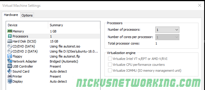
For these tests I created the baseline VM to run in VMWare Workstation with the below settings:
We’ll be transcoding using RTPengine, which recently added transcoding capabilities, so I set that up as per my post on setting up RTPengine for Transcoding.
Next I setup some SIPp scenarios to simulate call loads, from G.711 a-law to G.711 u-law (the simplest of transcoding (well re-compounding)) and used glances to get the max CPU usage and logged the results.
PCMA to PCMU (Re-companding)
PCMA to PCMU
RTPengine fared significantly better than I expected, I stopped at 150 concurrent transcoding sessions as that’s when call quality was really starting to degrade, but I was still achieving MOS of 4.3+ up to 130 concurrent sessions.
For what I needed to do, running this in a virtualised environment allowed 150 transcoding sessions before the MOS started to drop and call quality was adversely affected. Either way I was pretty amazed at how efficiently RTPengine managed to handle this.
Transcoding from one codec to a different codec was a different matter, and I’ll post the results from that another day.