Note: I’m lazily posting this as its been in my drafts folder for an exceedingly long time – Before going too much further, it’s worth pointing out that eMBMS never really made it anywhere – no production networks of note use eMBMS. I started researching it and my interest petered out once I discovered I couldn’t get any UEs or hardware that supported eMBMS.
Mobile networks are designed as point to point, all traffic is unicast.
But multicast and broadcast traffic is real, and becoming more common in some applications.
In areas where users stream the same radio program, or TV show, live, each of them is consuming the same data stream, but each one gets sent a unique copy of the data, on a resource block allocated to them for reception of the data.
If we have 10 users on a cell, each streaming a 5Mbps live video, that’s 50Mbps of capacity taken up on the radio / air interface. If that stream was moved onto a eMBMS service, only 5Mbps of capacity would be used, regardless of how many people on the cell are consuming it.
For Mission Critical Push to Talk applications, the lack of broadcast/multicast support was highlighted again. For a PTT app with 10 users in a talk group, you’d need to schedule resource blocks for 10 users, and allocate 10 radio resources 10 times, send GTP packets 10 times, all to send the same data to 10 people.
So enter eMBMS – The Evolved Multimedia Broadcast and Multicast Service, providing multicast service for LTE.
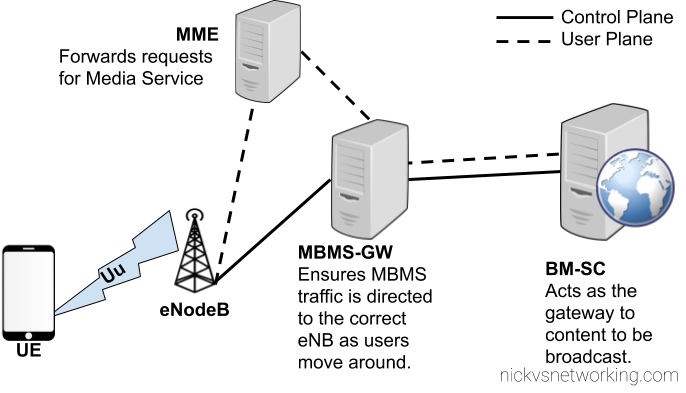
Overall Architecture
eMBMS introduces a few changes to the RAN side to handle support for a shared data channel, which is sent by the eNodeB and that UEs can listen on to get data. (More on admission control later)
From a core perspective two new network elements are introduced, the Broadcast/Multicast Service Center (BM-SC) and Multimedia Broadcast Multicast Services Gateway (MBMS GW), these elements function in much the same was the P-GW and S-GW retrospectively, but in regards to Multicast services.
Like so many 3GPP specs before it, MBMS relies on GTP for transporting the data to be distributed, and relies on GTPv2-C for control plane data.
BM-SC – Broadcast Media Service Centre
The Broadcast Multicast Service Centre acts as the gateway between content providers (providing streams of data to be distributed) and the EPC.
The BM-SC sets up eMBMS sessions and pulls broadcast data from the content providers and collects receipts from subscribers of some streams to charge / track consumption of the services.
In this regard the BM-SC is akin to the P-GW, which as the border for the EPC and external networks, except it’s largely unidirectional.
MBMS Gateway
The MBMS Gateway (MBMS-GW) encapsulates the broadcast data stream from the BM-SC and encapsulates it into GTP packets to be distributed to eNBs across the network.
The MBMS-GW allocates a multicast transport address for each broadcast data stream?
MME Interaction
For this a new interface is introduced on the MME – the Sm interface, which interconnects the MME and the MBMS-Gateways assigned to it.
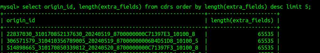
I started seeing this error the other day when running CDRsv1.GetCDRs on the CGrateS API:
SERVER_ERROR: unexpected end of JSON input
It seemed related to certain CDRs in the cdrs table of StoreDB.
After some digging, I found the stupid simple problem:
I’d written too much data to extra_fields, leading MySQL to cut off the data mid way through, meaning it couldn’t be reconstructed as JSON by CGrateS again.
Like the rounding issue I had, this wasn’t an issue with CGrateS but with MySQL.
Quick fix:
sudo mysql cgrates -e "ALTER TABLE cdrs MODIFY extra_fields LONGTEXT;"
And new fields can exceed this length without being cut off.
This post follows on from Part 1 and Part 2 of this 3 part series.
We are forced to move to 5G-SA
Claim: We must use 5G-SA with this spectrum (It’s a condition of the license)
I’ll concede that if it is a requirement for a license or funding, that 5G-SA be used, then that’s a pretty ironclad reason to introduce 5G-SA.
Claim: Users will Leave if you don’t have 5G-SA
We could argue the opposite effect will happen; Shifting to SA will reduce your user base. Here’s why:
Users experiencing 5G-NSA (Non-Standalone) today, are already getting the speed boost from “5G”.
From a user perspective, while 5G-NSA support has been becoming common on mid-to-high priced handsets, handsets supporting 5G-SA are far less common.
Dish’ Project Genesis is one of the only examples of a 5G SA network deployed on a large scale. It launched with only a single supported phone (A Motorola branded handset) and today the supported phone list is very short, limited to expensive flagships. This lack of handset support means users must purchase a handset through Dish rather than being able to bring their own phones, as the only way that compatibility can be guaranteed is by controlling the whole ecosystem.
Unless you are in a highly developed market with 2G and 3G turned off, where the majority of your user base has recent generation flagship phones capable of supporting these features, you’re shrinking your addressable market with 5G-SA, rather than expanding it.
Conclusion – 5G-SA doesn’t stack up, what do I do?
SA doesn’t make sense for a lot of operators and markets – for now. I’m sure this post will look pretty dated in a few years time as many of these factors change and as operators sunset 2G and 3G networks.
I’m not advocating for 5G-SA never, I’m advocating not 5G-SA today.
There are simply better options out there for spending that operations budget to make network improvements.
Off the bat some ideas to expore:
Optimize your existing network.
Roll out NSA to an even larger area.
Shutdown 2G/3G layers.
Simplify your operations.
Cut down the number of vendors and moving parts.
Simplify again.
Automate.
Simplify more.
Doing this will mean you can enjoy cost savings from reduced headcount thanks to a simpler network. Simpler networks have better up-time, thanks to operating a network that’s less frankensteiny – less cobbled together from disparate legacy parts. You’ll also Enjoy reduced opex from all the systems you’ve shut down and cheaper roaming from all the bilaterals you moved to VoLTE.
All of these tasks will keep project teams busy for years and put the MNO in a stronger position moving forward, without getting distracted by slick marketing and shiny brochures.
A totally complete history and not just something I learned from a fellow phone nerd who’s been around a lot longer than me...
In the early days of telephony voice calls were made by signaling to an operator who would connect your call.
Around the turn of the century the first “automatic” exchanges began to open. This meant that a subscriber could complete their own call, by directly dialing the digits of the party the want to speak to, and getting through, without a human operator “plugging up” the call.
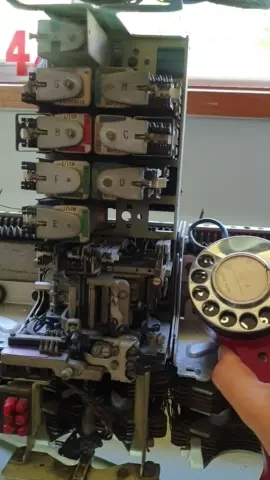
The first type of switches used to provide “automatic” exchange capability were Strowger type switches, they translated the pulses from a rotary dial phone into physical movements on a switch to find and select the line you want.
As it happens I have one of these old switches, here’s what happens when you let go of the dial.
People who were born before touch tone phones can tell you about how you can dial a phone number without using the dial at all. By mashing the hook switch really quickly. If you want to dial a 3 you mash the hook switch 3 times, then wait a second, then to dial a 5 smash the hook switch 5 times, etc, etc.
A quirk of this is that higher numbers, are harder to dial, you just need one pulse of the hook switch in a second to dial a 1, but you need 10 pulses to dial a 0. This means a phone dial that’s running too slow can dial the lower digits, but not the higher digits, as it can’t pulse out the required number of pulses is the time allotted (a smidge over 1 second per digit).
Initially exchanges only connected local calls, but with the introduction of Subscriber Trunk Dialing (STD), subscribers could call from one exchange to another without an operator.
This led to national dialing plans being developed, ensuring uniqueness of numbers across the whole of the phone network, and where possible, lower numbers were used, Australia for example has area codes 02, 03, 07 and 08 (with the majority of the population living in the 02 and 03 area codes).
Now imagine you’re the government owned phone company, tasked with creating a single number for emergency services, 123, 111, etc, etc, are all taken up, as these are the most reliable numbers to dial and were used long ago.
Instead you go to the other end, the UK with 999 and Australia with 000 (911 is a different kettle of fish).
Except in New Zealand.
111 was specifically chosen to be similar to Britain’s 999 service, but NZ has some odd peculiarities.
The NZ dials are identical to the standard dial except for the finger plate label.
With pulse dialing, New Zealand telephones pulse “in reverse” to the rest of the world. Dialing 0 on a phone in the rest of the world, sent ten pulses down the line. But dialing a 0 on a phone in NZ sent one pulse down the line. The same for all the other numbers. The phones weren’t different – Just the labels.
Hence the reason why ‘Emergency’ services were on 111 in NZ (but actually pulsed 999) as the exchanges originated in those days from the UK where 999 was (and still is 999).
In the early years of 111, the telephone equipment was based on British Post Office equipment, except for this unusual orientation. Therefore, dialing 111 on a New Zealand telephone sent three sets of nine pulses to the exchange, exactly the same as the UK’s 999.
PyHSS is our open source Home Subscriber Server, it’s written in Python, has a variety of different backends, and is highly perforate (We benchmark to 10K transactions per second) and infinitely scaleable.
In this post I’ll cover the basics of setting up PyHSS in your enviroment and getting some Diameter peers connected.
For starters, we’ll need a database (We’ll use MySQL for this demo) and an account on that database for a MySQL user.
So let’s get that rolling (I’m using Ubuntu 24.04):
sudo apt update
sudo apt install mysql-server
Next we’ll create the MySQL user for PyHSS to use:
CREATE USER 'pyhss_user'@'%' IDENTIFIED BY 'pyhss_password';
GRANT ALL PRIVILEGES ON *.* TO 'pyhss_user'@'%' WITH GRANT OPTION;
FLUSH PRIVILEGES;
We’ll also need Redis as well (PyHSS uses Redis for inter-service communications and for caching), so go ahead an install that for your distro:
sudo apt install redis-server
So that’s our prerequisites sorted, let’s clone the PyHSS repo:
And install the requirements with pip from the PyHSS repo:
pip3 install -r requirements.txt
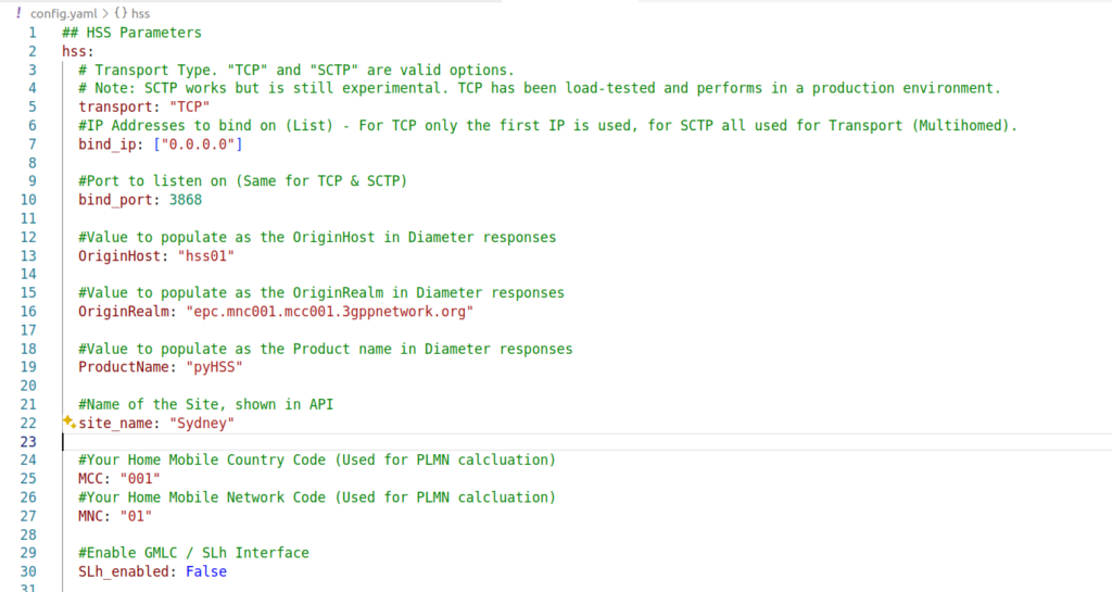
Next we’ll need to configure PyHSS, for that we update the config file (config.yaml) with the settings we want to use.
We’ll start by setting the bind_ip to a list of IPs you want to listen on, and your transport – We can use either TCP or SCTP.
For Diameter, we will set OriginHost and OriginRealm to match the Diameter hostname you want to use for this peer, and the Realm of your Diameter network.
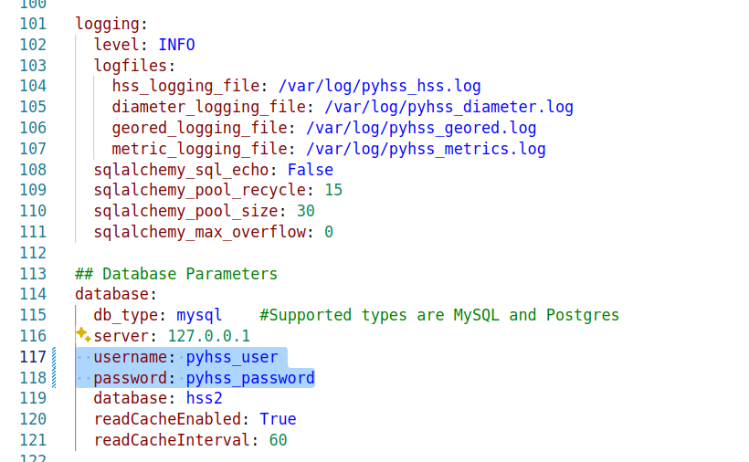
Lastly we’ll need to set the database parameters, updating the database: section to populate your credentials, setting your username and password and the database to match your SQL installation we setup at the start.
With that done, we can start PyHSS, which we do using systemctl.
Because there’s multiple microservices that make up PyHSS, there’s multiple systemctl files use to run PyHSS as a service, they’re all in the /systemd folder.
Like a lot of companies, we’re moving away from VMware, and in our case, shifting to Proxmox.
But that doesn’t mean we can get entirely away from VMware, but more that it’s not our hypervisor of choice anymore, and this means shifting our dev environments and lab off VMware to Proxmox first.
So today I sat down to try and shift everything to Proxmox, while keeping the VMware based VMs accessible until they can slowly die of bitrot.
A sane person would probably utilize Proxmox’s fancy new tool for migrating VMs from VMware to Proxmox, and it’s great, but in our case at least, it required logging into each VM and remapping NICs, etc, which is tricky on boxes I don’t have access to – Plus we need to keep some VMware capability for testing / labbing stuff up.
So I decided into install Proxmox onto the bare metal servers, and then create a VMware virtual machine inside the Proxmox stack, to host a VMware ESXi instance.
I started off inside VMware (Before installing any Proxmox) by moving all the VMs onto a single physical disk, which I then removed from the server, so as to not accidentally format the one disk I didn’t want to format.
Next I nuked the server and setup the new stack with Proxmox, which is a doddle, and not something I’ll cover.
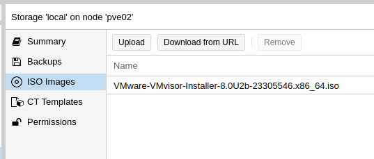
Then I loaded a VMware ISO into Proxmox and started setting up the VM.
Now, nested virtualization is a real pain in the behind.
VMware doesn’t like not being run on bare metal, and it took me a good long amount of time to find the hardware config that I could setup in Proxmox that VMware would accept.
Create the VM in the Web UI; I found using a SATA drive worked while SCSI failed, so create a SATA based LVM image to use, and mount the datastore ISO.
Then edit /etc/pve/qemu-server/your_id.conf and replace the netX, args, boot and ostype to match the below:
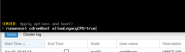
Now you can go and start the VM, but once you’ve got the VMware splash screen, you’ll need to press Shift + O to enter the boot options.
At the runweasle cdromBoot after it add allowLegacyCPU=true– This will allow ESXi to use our (virtual) CPU.
Next up you’ll install VMware ESXi just like you’ve probably done 100 times before (is this the last time?), and once it’s done installing, power off, we’ll have to make few changes to the VM definition file.
Then after install we need to change the boot order, by updating:
boot: order=sata0
And unmount the ISO:
ide2: none,media=cdrom
Now remember how I’d pulled the hard disk containing all the VMware VMs out so I couldn’t break it? Well, don’t drop that, because now we’re going to map that physical drive into the VM for VMware, so I can boot all those VMs.
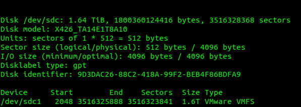
I plugged in the drive and I used this to find the drive I’d just inserted:
fdisk -l
Which showed the drive I’d just added last, with it’s VMware file system.
So next we need to map this through the VM we just created inside Proxmox, so VMware inside Proxmox can access the VMware file system on the disk filled with all our old VMware VMs.
VM. VM. VM. The word has lost all meaning to me at this stage.
We can see the mount point of our physical disk; in our case is /dev/sdc so that’s what we’ll pass through to the VM.
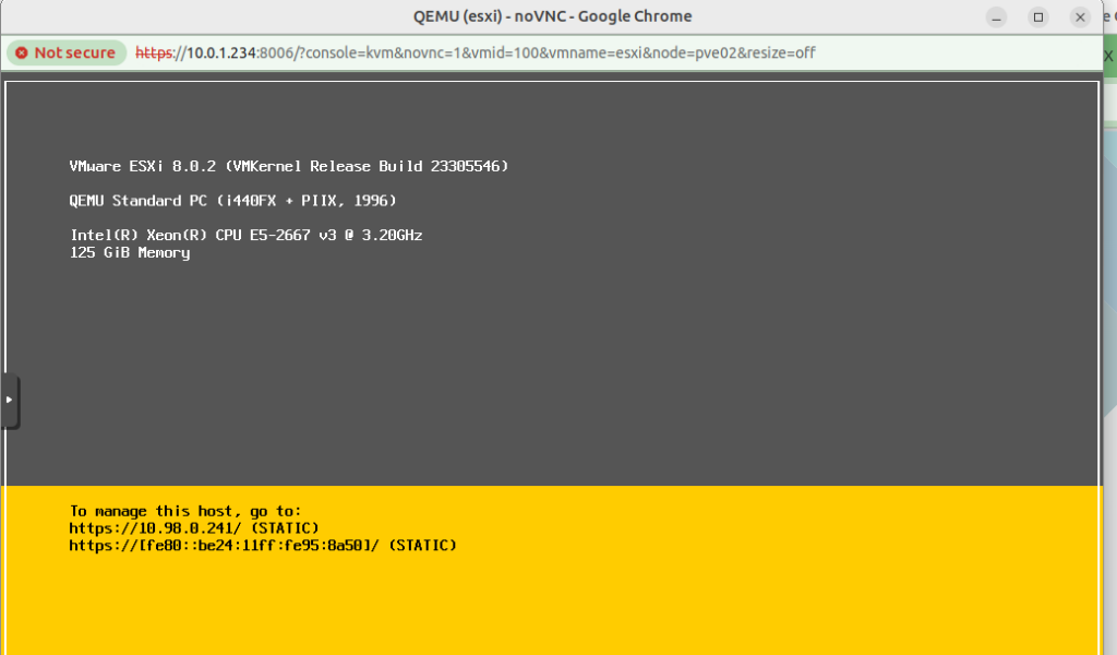
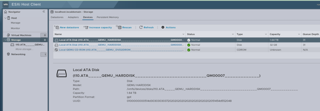
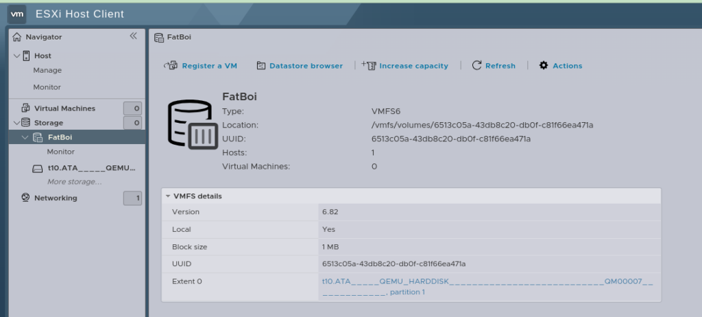
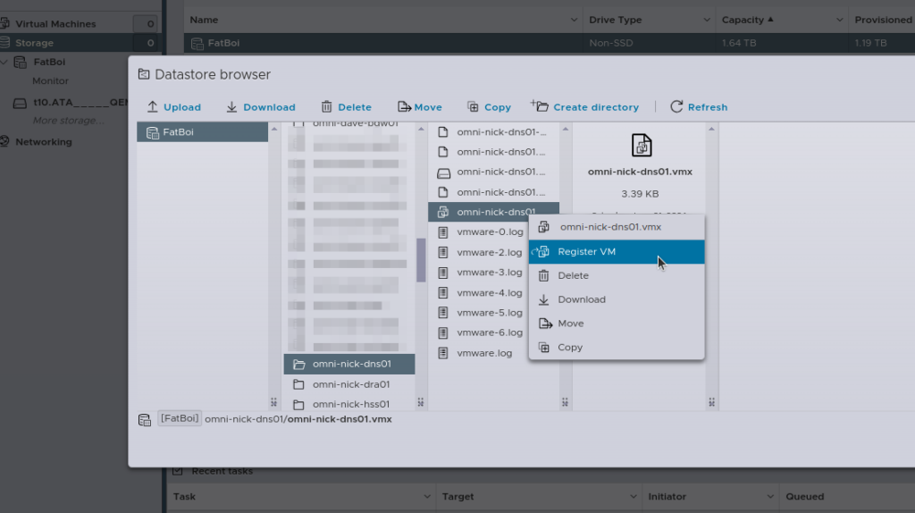
And now, if everything has gone well, after logging into the Web UI, you’ll see this:
Then the last step is going to be re-registering all the VMs, you can do this by hand, by selecting the .vmx file and adding it.
Alternately, if you’re lazy like me, I wrote a little script to do the same thing:
[root@localhost:~] cat load_vms3.sh


#!/bin/bash

# Datastore name
DATASTORE="FatBoi/"

# Log file to store the output
LOG_FILE="/var/log/register_vms.log"

# Clear the log file
> $LOG_FILE

echo "Starting VM registration process on datastore: $DATASTORE" | tee -a $LOG_FILE

# Check if datastore directory exists
if [ ! -d "/vmfs/volumes/$DATASTORE" ]; then
    echo "Datastore $DATASTORE does not exist!" | tee -a $LOG_FILE
    exit 1
fi

# Find all .vmx files in the datastore and register them
find /vmfs/volumes/$DATASTORE -type f -name "*.vmx" | while read VMX_PATH; do
    echo "Registering VM: $VMX_PATH" | tee -a $LOG_FILE
    vim-cmd solo/registervm "$VMX_PATH" | tee -a $LOG_FILE
done

echo "VM registration process completed." | tee -a $LOG_FILE

[root@localhost:~] sh load_vms3.sh
Now with all your VMs loaded, you should almost be ready to roll and power them all back on.
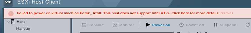
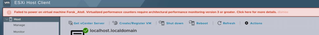
But before we reboot the Hypervisor (Proxmox) we’ll have to reboot the VMware hypervisor too, because here’s something else to make you punch the screen:
Luckily we can fix this one globaly.
SSH into the VMware box, edit /etc/vmware/config.xml file and add:
vhv.enable = "FALSE"
Which will disable the performance counters.
Now power off the VMware VM, and reboot the Proxmox hypervisor, when it powers on again, Proxmox will allow nested virtualization, and when you power back on the VMware VM, you’ll have performance counters disabled, and then, you will be done.
Yeah, not a great use of my Saturday, but here we are…
Want more telecom goodness?
I have a good old fashioned RSS feed you can subscribe to.