Monthly Archives: July 2020

Viewing the SIB – The LTE System Information Block with SDRs

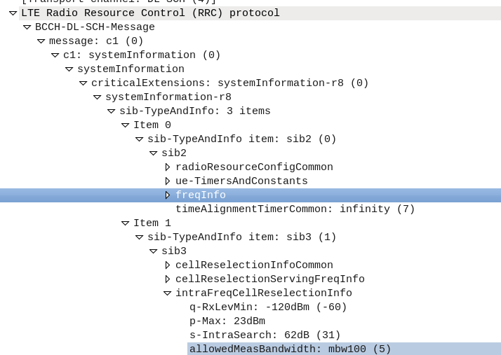
I’ve been experimenting with Inter-RAT & Inter-Frequency handovers recetly, and had an issue where what I thought was configured on the eNB I wasn’t seeing reflected on the UEs.

I understood the Neighbouring Cell reelection parameters are broadcast in the System Information Blocks, but how could I view them?

The answer – srsUE!

I can’t get over how cool the stuff coming out of Software Radio Systems is, but being able to simulate a UE and eNB on SDR hardware is pretty awesome, and also allows you to view low layer traces the vast majority of commercial UEs will never expose to a user.

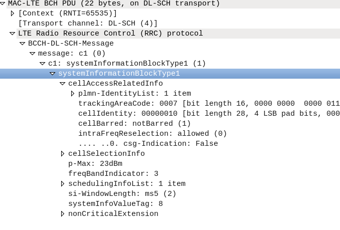
After running srsUE with the PCAP option I let it scan for networks and find mine. I didn’t actually need to authenticate with the network, just lock to the cell.

Deocoding it using the steps I laid out here for decoding LTE MAC traces in Wireshark, there it all was!

I’ve attached a copy of the pcap here for your reference.

GSM with Osmocom: GPRS & Packet Data

So far we’ve focused on building a plain “2G” (voice and SMS only) network, which was all consumers expected twenty years ago.

As the number of users accessing the internet through DSL, Dial Up & ISDN grew, the idea of getting this data “on the go” became more appealing. TCP/IP was becoming the dominant standard for networking, the first 802.11 WiFi spec had recently been published and demand for mobile data was growing.

There’s a catch however – TCP/IP was never designed to be mobile.

An IP address exists in a single location.

(Disclaimer: While you can “move” a subnet by advertising itself out in a different location via BGP peering relationships with other operators, it’s cumbersome, can only be done per /24 or larger, and most importantly it’s painfully slow. IPv6 has MIPv6 which attempts to fix some of these points, but that’s outside of this scope.)

GPRS addressed the mobility issue by having a single fixed point the IP Address is assigned to (the Gateway GPRS Support Node), which encapsulates IP traffic to/from a mobile user into GTP Packet (GPRS Tunnelling Protocol), like GRE or any of the other common routing encapsulation protocols, allowing the traffic to be rerouted to different destinations as the users move from being served by one BTS to another BTS.

I’ve written about GTP here if you’d like to learn more.

So now we’ve got a method of encapsulating our data we’ve got to work out how to get that data out over the air.

BTS Time Slots

Way back when we were first setting up our BSC and adding our BTS(s) you will have configured timeslots for each BTS configured on your BSC.

Chances are if you’ve been following along with this tutorial, that you configured the first time slot (timeslot 0) as a CCCH+SDCCH4, meaning Common Control Channel and 4 standalone dedicated control channels, and all the subsequent timeslots (timeslot 1 – 7) as Traffic Channels (full rate) – TCH/F.

This works well if we’re only carrying voice, but to carry data we need timeslots to put the data traffic on.

For this we’ll re assign a timeslot we were using on our BSC as a voice traffic channel (TCH/F) as a PDCH – a Packet Data Channel.

This means that on the BSC your timeslot config will look something like this:

   timeslot 6
    phys_chan_config PDCH
    hopping enabled 0
   timeslot 7
    phys_chan_config PDCH
    hopping enabled 0

In the above example I’ve assigned two timeslots for Packet Data Channels,

The more timeslots you allocate for data, the more bandwidth available, but the fewer voice resources available.

(Most GSM networks today have few data timeslots as more recent RATs like 3G/4G are taking the data traffic, and GSM is used primarily for voice and low bandwidth M2M communications)

GPRS and EDGE

GPRS comes in two flavors, GPRS and EDGE.

GPRS (General Packet Radio Services) was the first of the two, standardised in R97, and allowed users to reach a downlink speeds of up to 171Kbps using GMSK on the air interface to encode the data.

Users quickly expected more speed, so EDGE (Enhanced Data rates for Global Evolution) was standardised, from a core perspective it was the same, but from a BTS / Air interface perspective it relied on 8PSK instead of GMSK allowed users to reach a blistering 384Kbps on the downlink.

These speeds are the theoretical maximums.

As the difference between GPRS and EDGE is encoding on the air interface, from a core perspective it’s treated the same way, however as our BTS gets all it’s brains from the BSC, we’ll need to specify if the BTS should use EDGE or GPRS it in the BSC’s BTS config.

BSC Config

On the BSC for each BTS we want to enable for packet data, we’ll need to define the parameters.

There’s two other values we’ll introduce when setting this up,

The first is NSEI – the Network Service Entity Identifier, which is the identifier of the BTS’s Packet Control Unit, like the cell identity.

The second value we’ll touch on is the BVCI – the BSSGP Virtual Connections Identifier, which is used for addressing between the BTS PCU and the SGSN.

bts 0
  gprs mode egprs
  gprs 11bit_rach_support_for_egprs 0
  gprs routing area 0
  gprs network-control-order nc0
  gprs cell bvci 2
  gprs cell timer blocking-timer 3
  gprs cell timer blocking-retries 3
  gprs cell timer unblocking-retries 3
  gprs cell timer reset-timer 3
  gprs cell timer reset-retries 3
  gprs cell timer suspend-timer 10
  gprs cell timer suspend-retries 3
  gprs cell timer resume-timer 10
  gprs cell timer resume-retries 3
  gprs cell timer capability-update-timer 10
  gprs cell timer capability-update-retries 3
  gprs nsei 101
  gprs ns timer tns-block 3
  gprs ns timer tns-block-retries 3
  gprs ns timer tns-reset 3
  gprs ns timer tns-reset-retries 3
  gprs ns timer tns-test 30
  gprs ns timer tns-alive 3
  gprs ns timer tns-alive-retries 10
  gprs nsvc 0 nsvci 101
  gprs nsvc 0 local udp port 23001
  gprs nsvc 0 remote udp port 23000
  gprs nsvc 0 remote ip 10.0.1.201

The OsmoBSC docs cover each of these values, they’re essentially defaults.

There are quite a few changes required on the BSC for each BTS we’re setting this up for. Instead of giving you info on what fields to change, here’s the diffs.

In the next post we’ll cover the GGSN and the SGSN and then getting a device on “the net”.
GSM with Osmocom: SS7 & Sigtran

SS7 was first introduced in the 1970s and initially was designed for large scale setting up and tearing down of calls, but due to it’s layered architecture and prominence in the industry has been used for signalling between some CS network elements in Mobile Networks, including transporting messages between the MSC and any BSCs or RNCs it’s serving.

This is going to be fairly brief and Osmocom specific, keep in mind SS7 is a giant topic so there’s a huge amount we won’t cover.

Point Codes – SS7 Addressing & Routing

Historically SS7 networks were carried over TDM links of various types, and not over TCP/IP.

A point code is a unique address associated with each network element for addressing messages between network elements, it’s function is similar to that of an IP Address you’d use in IP networks.

When STP messaging is sent it includes a Source Point Code (SPC) and Destination Point Code (DPC).

The Signalling Transfer Point

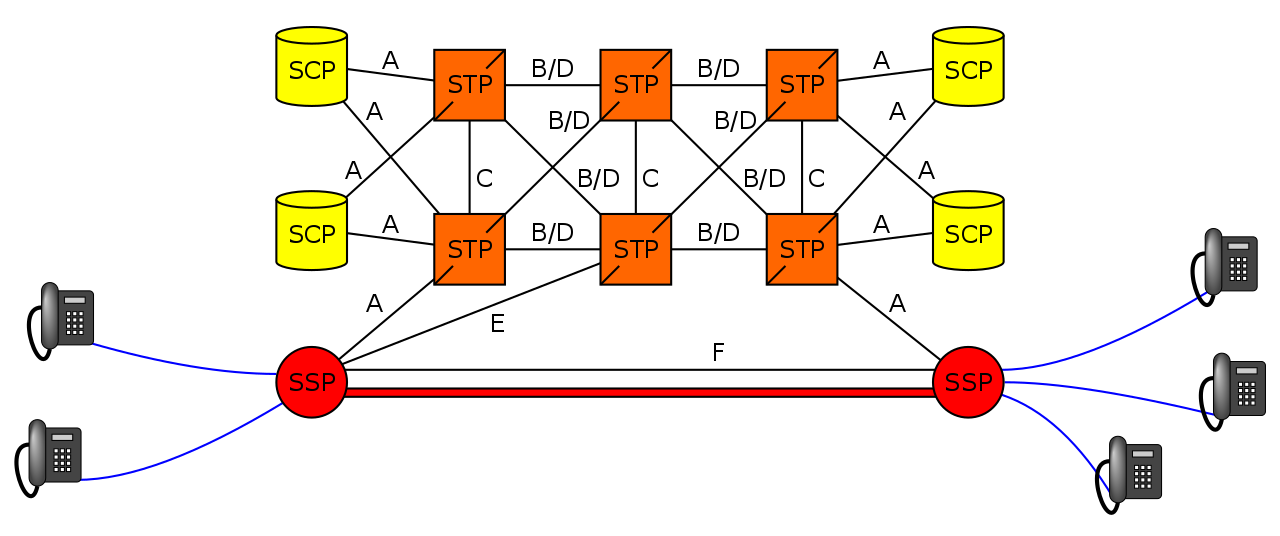
Instead of a one-to-one connection between each SS7 device and every other SS7 device, a network element called a Signaling Transfer Point (STP) is used, which acts somewhat like a router.

The STP has an internal routing table made up of the Point Codes it has connections to and some logic to know how to get to each of them.

When it receives an SS7 message, the STP looks at the Destination point code, and finds if it has a path to that point code. If it does, it forwards the SS7 message on to the destination.

Like a router, an STP doesn’t really concern itself with the upper layer protocols and what they contain – As point codes are set in the MTP3 layer that’s the only layer the STP looks at and the upper layers aren’t really “any of its business”.

Sigtran & SS7 Over IP

As the world moved towards IP enabled everything, TDM based Sigtran Networks became increasingly expensive to maintain and operate, so a IETF taskforce called SIGTRAN was created to look at moving SS7 traffic to IP.

The first layer of SS7 were dropped it primarily concerned the physical side of the network, and in the Osmocom implementation the MTP3 layer and up were put into SCTP packets and carried on the network.

Notice I said SCTP and not TCP or UDP? I’ve touched upon SCTP on this blog before, it’s as if you took the best bits of TCP without the issues like head of line blocking and added multi-homing of connections.

To establish an SS7 connection over IP the MTP3 message an SCTP socket is established from the device to the STP, and then an ASP Maintenance message is sent, followed by a Registration Request containing it’s point code, and presto, we have a connection.

The Osmo STP

The Osmocom STP acts in a very trusting manner by default,

When a device wants to connect to the STP it does so via a REG_REQ (Registration Request) containing it’s Point Code. The STP accepts the connection with a REG_RSP (Registration Response).

For as long as that connection stays up any SS7 messages destined to that point code of the device that just registered, the STP will now how to get it there.

Assuming you’ve already installed the OsmoSTP you can access it on 4239:

root@gsm-bts:/etc/osmocom# telnet localhost 4239
Trying 127.0.0.1…
Connected to localhost.
Welcome to the OsmoSTP VTY interface
OsmoSTP>

After running enable we can check the current routing table:

OsmoSTP# show cs7 instance 0 sccp users
SS7 instance 0 has no SCCP
OsmoSTP# show cs7 instance 0 ro
OsmoSTP# show cs7 instance 0 route
Routing table = system
C=Cong Q=QoS P=Prio
Destination C Q P Linkset Name Linkset Non-adj Route

0.23.1/14 0 as-rkm-1 ? ? ?
0.23.3/14 0 as-rkm-2 ? ? ?

OsmoSTP# show cs7 instance 0 as all
Routing Routing Key Cic Cic Traffic
AS Name State Context Dpc Si Opc Ssn Min Max Mode

as-rkm-1 AS_ACTIVE 1 0.23.1 override
as-rkm-2 AS_ACTIVE 2 0.23.3 override

OsmoSTP# show cs7 instance 0 asp
Effect Primary
ASP Name AS Name State Type Remote IP Addr:Rmt Port SCTP
------------ ------------ ------------- ---- ----------------------- ----------
asp-dyn-0 ? ASP_ACTIVE m3ua 127.0.0.1:52192
asp-dyn-1 ? ASP_ACTIVE m3ua 127.0.0.1:33570

Packet Capture

Below is a packet capture showing a connection from an MSC to the STP.

FreeSWITCH + ESL = Programmable Voice

No great secret, I’m a big Python fan.

Recently I’ve been working on a few projects with FreeSWITCH, and looking at options for programmatically generating dialplans, instead of static XML files.

Why not Static XML?

So let’s say I define a static XML dialplan.

It works great, but if I want to change the way a call routes I need to do it from the dialplan,

That’s not ideal if you’re using a distributed cluster of FreeSWITCH instances, or if you want to update on the fly.

Static XML means we have to define our dialplan when setting up the server, and would have to reconfigure the server to change it.

So what about mod_xml_curl?

When I’ve done this in the past I’ve relied on the mod_xml_curl module.

mod_xml_curl gets the XML dialplan using Curl from a web server, and so you setup a web server using Flask/PHP/etc, and dynamically generate the dialplan when the call comes in.

This sounds good, except you can’t update it on the fly.

mod_xml_curl means call routing decisions are made at the start of the call, and can’t be changed midway through the call.

So what’s ESL?

ESL is the Event Socket Library, essentially a call comes in, an ESL request is made to an external server.

For each step in the dialplan, an ESL request will be sent to the external server which tells it to do,

ESL allows us to use all FreeSWITCH’s fantastic modules, without being limited as to having to perform the call routing logic in FreeSWITCH.

So how do I use ESL?

You’ll need two create an ESL server,

Luckily there’s premade examples for popular languages;

Once you’ve got a basic server defined we’ll need to put some config in our XML Dialplan to say “transfer all your thinking to ESL!”;

<!-- Send everything that's numbers to ESL for Processing --> 
    <extension name="esl_route">
      <condition field="destination_number" expression="^\d*$">
        <action application="socket" data="10.0.1.252:5000"/>
        <action application="log" data="ERR Made it past ESL - Play error."/>
        <action application="playback" data="ivr/ivr-call_cannot_be_completed_as_dialed"/>
      </condition>
    </extension>

In the above example my ESL server is on 10.0.1.252 / port 5000.

Now any calls coming in will be transfered to ESL and where it goes from there, is something you define in your prefered programming language.

In the next post I’ll cover how I’ve been addressing this using Python and Greenswitch.

Open5Gs Logo

Open5GS EPC: SGW selection by eNodeB ID / TAC

Thanks to Kenny Barlee the Open5GS EPC MME now has the functionality to select which S-GW to send traffic to based on the Tracking Area Code of the eNodeB or the eNodeB ID.

This is a really useful Feature that allows you to break up your S-GW (And by extension P-GW) selection based on geographical areas.

This can be used to enable Local Breakout to a S/P-GW located at the same site as the tower, but controlled by a central MME / HSS.

After updating to the latest version the configuration is pretty straightforard,

P-GW Selection based on eNB ID

# o SGW selection by eNodeB ID (either single enb_id or multiple enb_ids, decimal or hex representation)
#
   selection_mode: enb_id
   gtpc:
     - addr: 127.0.2.3
       enb_id: [9413, 0x98765]

The above config will send any traffic from eNBs with the eNB ID 9413 (encoded as an intiger) or 0x98765 (Encoded as hex int equivilent 624485) to an S-GW at 127.0.2.3.

P-GW Selection based on TAC

# SGW selection by eNodeB TAC (either single TAC or multiple TACs)
#
selection_mode: tac
   gtpc:
     - addr: 127.0.2.2
       tac: [25000, 27000, 28000]

The above config will send any traffic from eNBs with TACs of 25000, 27000, 28000 to an S-GW at 127.0.2.2.

Diameter Dispatches – Origin-State-Id AVP

The Origin-State-Id AVP solves a kind of tricky problem – how do you know if a Diameter peer has restarted?

It seems like a simple problem until you think about it.
One possible solution would be to add an AVP for “Recently Rebooted”, to be added on the first command queried of it from an endpoint, but what if there are multiple devices connecting to a Diameter endpoint?

The Origin-State AVP is a strikingly simple way to solve this problem. It’s a constantly incrementing counter that resets if the Diameter peer restarts.

If a client receives a Answer/Response where the Origin-State AVP is set to 10, and then the next request it’s set to 11, then the one after that is set to 12, 13, 14, etc, and then a request has the Origin-State AVP set to 5, the client can tell when it’s restarted by the fact 5 is lower than 14, the one before it.

It’s a constantly incrementing counter, that allows Diameter peers to detect if the endpoint has restarted.

Simple but effective.

You can find more about this in RFC3588 – the Diameter Base Protocol.

BaiCells USIM PLMN Issues (MCC 314 / MNC 030 vs MCC 311 / MNC 98)

If you’re using BaiCells hardware you may have noticed the new eNBs and USIMs are shipping with the PLMN of MCC 314 / MNC 030.

First thing I do is change the PLMN, but I was curious as to why the change.

It seems 314 / 030 was never assigned to BaiCells to use and when someone picked this up they were forced to change it.

The MCC (Mobile Country Code) part is dictated by the country / geographic area the subscribers’ are in, as defined by ITU, whereas the MNC (Mobile Network Code) allocation is managed by the regional authority and ITU are informed as to what the allocations are and publish in their bulletins.

ITU advertised this in Operational Bulletin No. 1198 (15.VI.2020)

What does this mean if you’re a BaiCells user?

Well, SIM cards will have a different IMSI / PLMN, but the hardware supports Multi-Operator Core Network which allows one eNB to broadcast multiple PLMNs, so if you update your eNB it can broadcast both!

I’ve written more about that in my post on MOCN.

Kamailio Bytes – UAC – Authenticate Outbound Calls

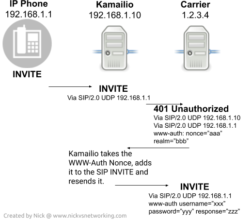
Sometimes you need Kamailio to serve as a User Agent Client, we covered using UAC to send SIP REGISTER messages and respond with the authentication info, but if you find you’re getting 401 or 407 responses back when sending an INVITE, you’ll need to use the UAC module, specifically the uac_auth() to authenticate the INVITE,

When Kamailio relays an INVITE to a destination, typically any replies / responses that are part of that dialog will go back to the originator using the Via headers.

This would be fine except if the originator doesn’t know the user name and password requested by the carrier, but Kamailio does,

Instead what we need Kamailio to do is if the response to the INVITE is a 401 Unauthorised Response, or a 407 Proxy Authentication required, intercept the request, generate the response to the authentication challenge, and send it to the carrier.

To do this we’ll need to use the UAC module in Kamailio and set some basic params:

loadmodule "uac.so"
modparam("uac", "reg_contact_addr", "10.0.1.252:5060")
modparam("uac", "reg_db_url", DBURL)
modparam("uac","auth_username_avp","$avp(auser)")
modparam("uac","auth_password_avp","$avp(apass)")
modparam("uac","auth_realm_avp","$avp(arealm)")

Next up when we relay the INVITE (using the Transaction module because we need the response to be transaction stateful).

Before we can call the t_relay() command, we need to specify a failure route, to be called if a negative response code comes back, we’ll use one called TRUNKAUTH and tell the transaction module that’s the one we’ll use by adding t_on_failure(“TRUNKAUTH”);

	$du = "sip:sip.nickvsnetworking.com:5060";
	if(is_method("INVITE")) {
		t_on_failure("TRUNKAUTH");
		t_relay();
		exit;
	   }

What we’ve done is specified to rewrite the destination URI to sip.nickvsnetworking.com, if the request type is an INVITE, it’ll load a failure route called TRUNKAUTH and proxy the request with the transaction module to sip.nickvsnetworking.com.

What we get is a 401 response back from our imaginary carrier, and included in it is a www-auth header for authentication.

To catch this we’ll create an on failure route named “TRUNKAUTH”

failure_route[TRUNKAUTH] {
    xlog("trunk auth");
    }

We’ll make sure the transaction hasn’t been cancelled, and if it has bail out (no point processing subsequent requests on a cancelled dialog).

failure_route[TRUNKAUTH] {
    xlog("trunk auth");
    if (t_is_canceled()) {
        exit;
    }

And determine if the response code is a 401 Unauthorised Response, or a 407 Proxy Authentication required (Authentication requests from our upstream carrier):

failure_route[TRUNKAUTH] {
    xlog("trunk auth");
    if (t_is_canceled()) {
        exit;
    }
	xlog("Checking status code");
    if(t_check_status("401|407")) {
	xlog("status code is valid auth challenge");
    }
}

Next we’ll define the username and password we want to call upon for this challenge, and generate an authentication response based on these values using the uac_auth() command,

failure_route[TRUNKAUTH] {
    xlog("trunk auth");
    if (t_is_canceled()) {
        exit;
    }
	xlog("Checking status code");
    if(t_check_status("401|407")) {
	xlog("status code is valid auth challenge");
        $avp(auser) = "test";
        $avp(apass) = "test";
        uac_auth();

    }
}

Then finally we’ll relay that back to the carrier with our www-auth header populated with the challenge response;

failure_route[TRUNKAUTH] {
    xlog("trunk auth");
    if (t_is_canceled()) {
        exit;
    }
	xlog("Checking status code");
    if(t_check_status("401|407")) {
	xlog("status code is valid auth challenge");
        $avp(auser) = "test";
        $avp(apass) = "test";
        uac_auth();
	xlog("after uac_auth");
        t_relay();
        exit;
    }
}

And done!

We can get this data from the UAC database so we don’t need to load these values directly into our config file too using the SQLops module.

As always I’ve put the running code example on my GitHub.