We were testing international roaming for a customer, roaming into the US where one of our team members (shoutout to Cody) is based.
So we sent Cody some SIMs and asked them to run the basic tests for us, but no IMS APN would attach.
We’d get them to power up the phone, fire up a trace on the roaming PGWs, but never seeing an attempt to attach on the IMS APN (No Create Session Request from the SGW in the vPMN).
The operator we were roaming into swore their side was correct – that IMSI was allowed for the IMS APN for testing, but whenever we’d run a trace, same thing, default bearer just fine but no CSR for the IMS APN, as if the IMS APN was blocked on the roaming network (Which is common on networks where you haven’t launched VoLTE but do have data roaming).
The steps we would do is:
Person in the US turns on phone tries to attach
I fire up my computer, get a trace running
Person in the US airplanes the device
I monitor for CSRs on the PGWs for that IMSI
But no CSR for the IMS APN would ever come through.
After a few attempts, here’s what we found was happening:
The phone would get powered up
The phone would roam onto the vPMN in the US and the default bearer would come up
The phone would try to attach to the ims APN, this would work for this SIM which was whitelisted, and the Create Session Request for the ims APN went to the PGW in the hPMN
The ims APN came up as expected
The phone would send a SIP REGISTER (So far so good)
Our IMS had an issue with Rx routing in this scenario, so the SIP REGISTER would timeout, and when it timed out, a 504 error was sent back to the phone by the P-CSCF and it set the Retry-After header to 3600 seconds.
The phone would not try again for as long as that timer value was set.
At this point we’d start a trace, airplane the device, and see no IMS APN attach attempt.
This 504 Timeout would all happen when the phone fired up before we had any traces running, so we weren’t capturing that.
I’d wrongly assumed that airplaning the device after starting a trace would reset the state fully, but it doesn’t, neither does a restart of the phone.
When we’d started a trace and airplane the phone, the phone wouldn’t try to attach to the ims APN as it was still inside the Retry-After time window from when we’d first fired it up.
Per RFC 3261, the phone should not try again during this time, which in our case meant no attempt to attach to the IMS APN, this makes sense – it protects the network against the thundering herd problem, but made this otherwise simple fault really hard to find.
CAMEL is primarily focused on charging for Voice & SMS services, as data generally uses Diameter, so it’s voice and SMS we’ll focus on.
CAMEL is spoken between the MSC (gsmSSF) and the OCS (gsmSCF).
Basic Call State Model
CAMEL is closely related to the Intelligent Network stuff on the 1980s, and steals a lot of it’s ideas from there, unfortunately if you’re to read the CAMEL standard it also implies you were involved in IN stuff and had been born at that point, alas I was neither.
So the key to understanding CAMEL is the Basic Call State Model (BCSM) which is a model of all the different states a call can be in, such as ringing, answered, abandoned, call failed, etc, etc.
Over CAMEL, our OCS can be told by the MSC when a certain event happens; the MSC can tell the OCS, that the call has changed state. For example a BCSM event might indicate the call has hung up, is ringing, cancelled, etc.
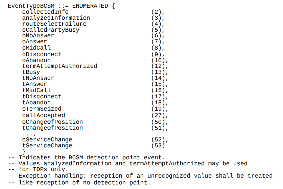
Below is the list of all the valid BCSM states:
List of BCSM states for events
Basic MO Call with CAMEL
Our subscriber makes an outbound call.
Based on the data the MSC has in it from the HLR, it knows that we should use CAMEL for this call, and it has the SCCP Address of the OCS (gsmSCF) it needs to send the CAMEL messages to.
So the MSC sends an InitialDP message to the OCS (via it’s Global Title Address) to Authorize the call that the user is trying to make.
This is like any other Authorization step for an OCS, which allows the OCS to authorize the call by checking the subscriber is valid, check if they’re allowed to call that destination and they’ve got the balance to do so, etc.
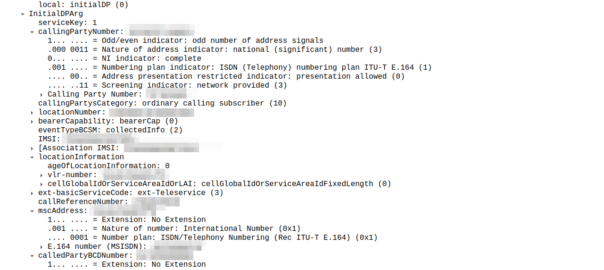
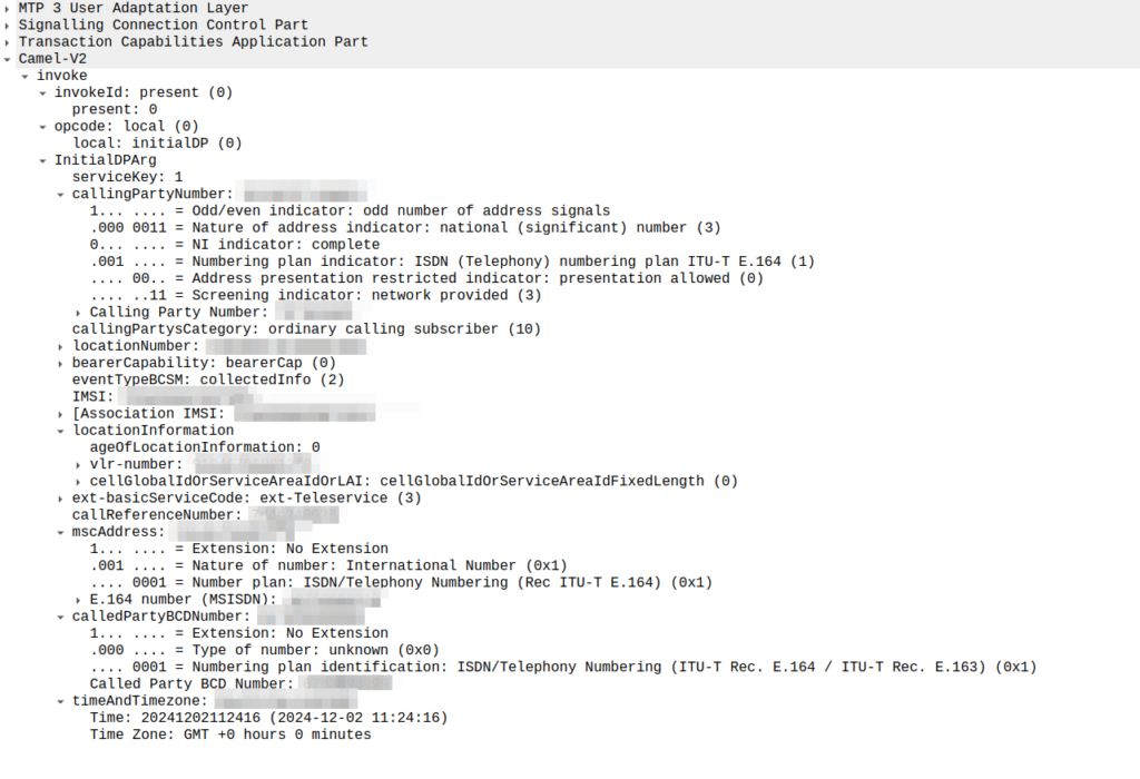
initialDP message from an MSC to an OCS
The initialDP (Initial Detection Point) is telling our OCS all about the call event that’s being requested, who’s calling, what number they’ve dialed, where they are in the network (of note especially if they’re roaming), etc, etc.
Generally the OCS also uses this message as a chance to subscribe to BCSM Events using RequestReportBCSMEventArg so the OCS will get notified by the MSC when the state of the call changes. This means the MSC will tell us when the state of the call changes; events like the call getting answered, disconnected, etc. This is critical so we know when the call gets answered and hung-up, so we can charge correctly.
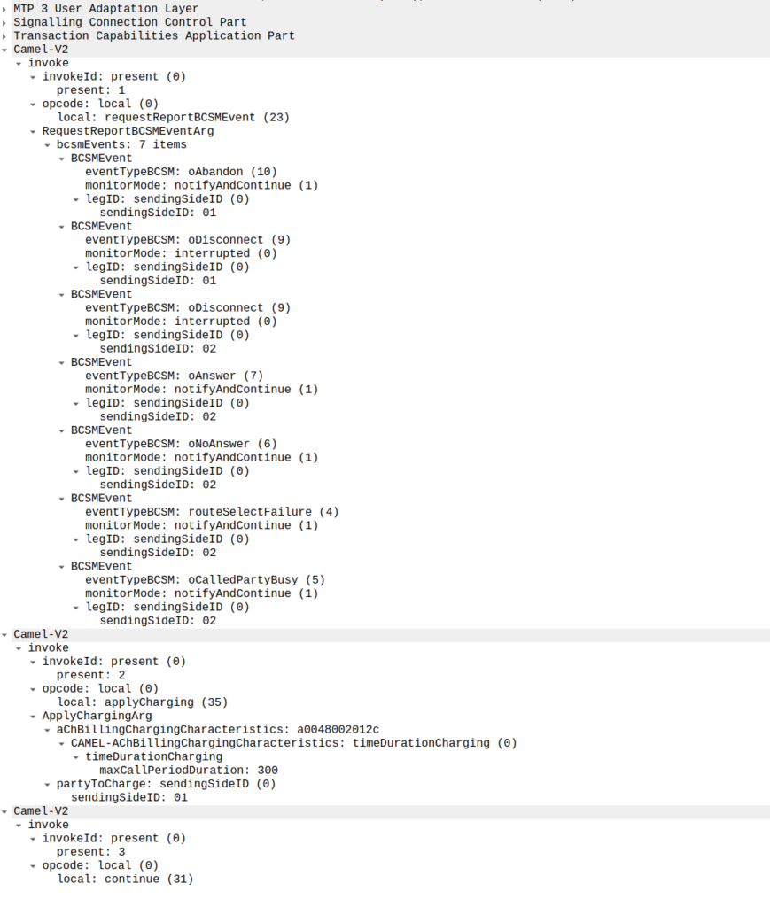
In the below example, as well as sending the Continue and RequestReportBCSMEventArg the OCS is also setting the ChargingArgs for this call, so the MSC knows who to charge (the caller) set via sendingSide and that the MSC must send an Apply Charging Report (ACR) messages every 300 units (1 unit = 100 ms, so a value of 300 = 300 x 100 milliseconds = 30 seconds) so the OCS keeps track of what’s going on.
continue sent by the OCS to the MSC, also including reportBCSMEvent and applyCharging messages
Or in a slightly less appropriate analogy but easier to understand for SIP folks, the InitialDP is sent for INVITE and the 180 RINGING is sent once the continue message is received.
Call is Answered
So at this stage our call can start to ring.
As we’ve subscribed to BCSM events in our last message, the MSC is going to tell us when the call gets answered or the call times out, is abandoned or the sun burns out.
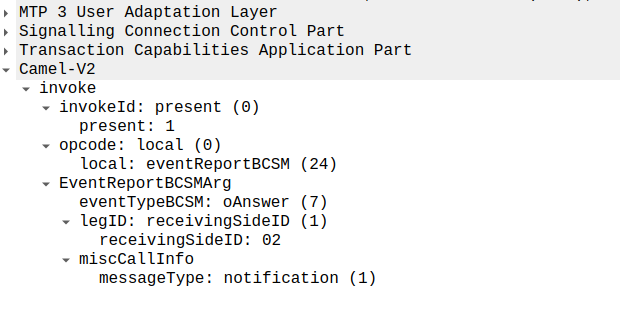
The MSC provides this info a eventReportBCSM, which is very simple and just tells us the event that’s been triggered, in the example below, the call was answered.
eventReportBCSM from MSC to OCS
These eventReportBCSM are informational from the MSC to the OCS, so the OCS doesn’t need to send anything back, but the OCS does need to mark the call as answered so it can start timing the call.
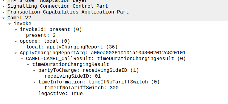
At this stage, the call is connected and our two parties are talking, but our MSC has been told it needs to send us applyChargingReports every 30 seconds (due to the value of 300 in maxCallPeriodDuration) after the call was connected, so the MSC sends the OCS it’s first applyChargingReport 30 seconds after the call was answered:
applyChargingReport sent by the MSC to the OCS every reporting period
We can calculate the duration of the call so far based on the time of the eventReportBCSM, then the OCS must make a decision of if it should allow the call to continue or not.
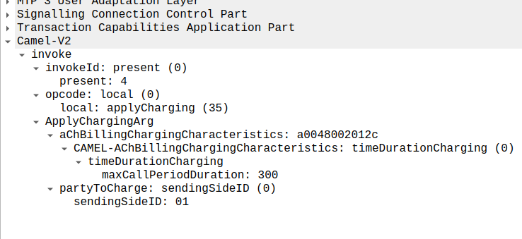
For simplicity’s sake, let’s imagine we’re still got a balance in the OCS and the OCS wants the call to continue, the OCS send back an applyCharging message to the MSC in response, and includes the current allowed maxCallPeriodDuration, keeping in mind the value is x100 and in nanoseconds (so this is 30 seconds).
applyCharging from the OCS back to the MSC
Perfect, our call is good to go for another 30 more seconds, son in 30 seconds we’ll get another ACR messages from MSC to the OCS to keep it abreast of what’s going on.
Now one of two things is going to happen, either subscriber is going to burn through all of their minutes, and get their call cutoff, or the call will end while they’ve still got balance, let’s look at both scenarios.
Normal Hangup Scenario
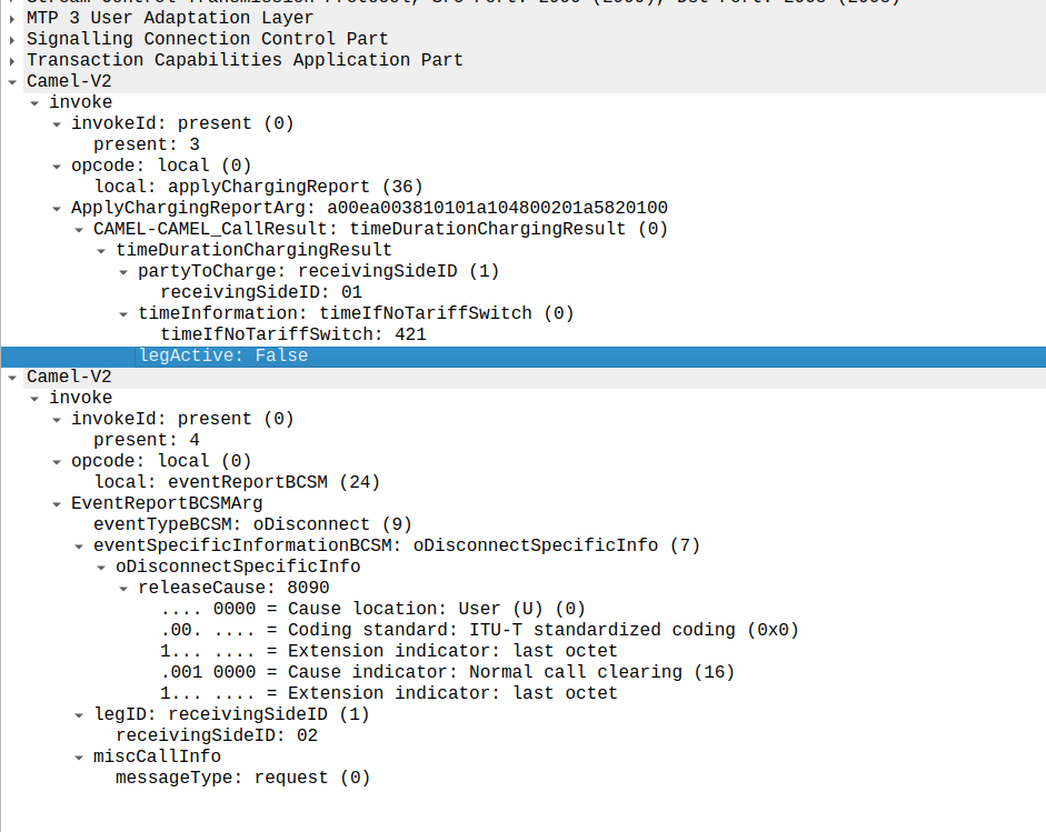
When the call ends, we get an applyChargingReport from the MSC to the OCS.
As we’ve subscribed to reportBCSMEvent we get both the applyChargingReport with legActive: False` so we know the call has hungup, and we’ve got an event report to tell us more about the event, in this case a hangup from the Originating Side.
reportBCSMEvent and applyChargingReport Sent by the MSC to the OCS to indicate the call has ended, note the legActive flag is now false
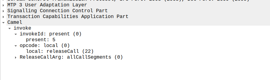
Lastly the OCS confirms by sending a releaseCall to the MSC, to indicate all legs should now terminate.
releaseCall Sent by OCS to MSC at the very end
So that’s it!
Obviously there are other flows, such as running out of balance mid-call, rejecting a call, SMS and PBX / VPN services that rely on CAMEL, but hopefully you now understand the basics of how CAMEL based charging looks and works.
If you’re looking for a CAMEL capable OCS or a CAMEL to Diameter or API gateway, get in touch!
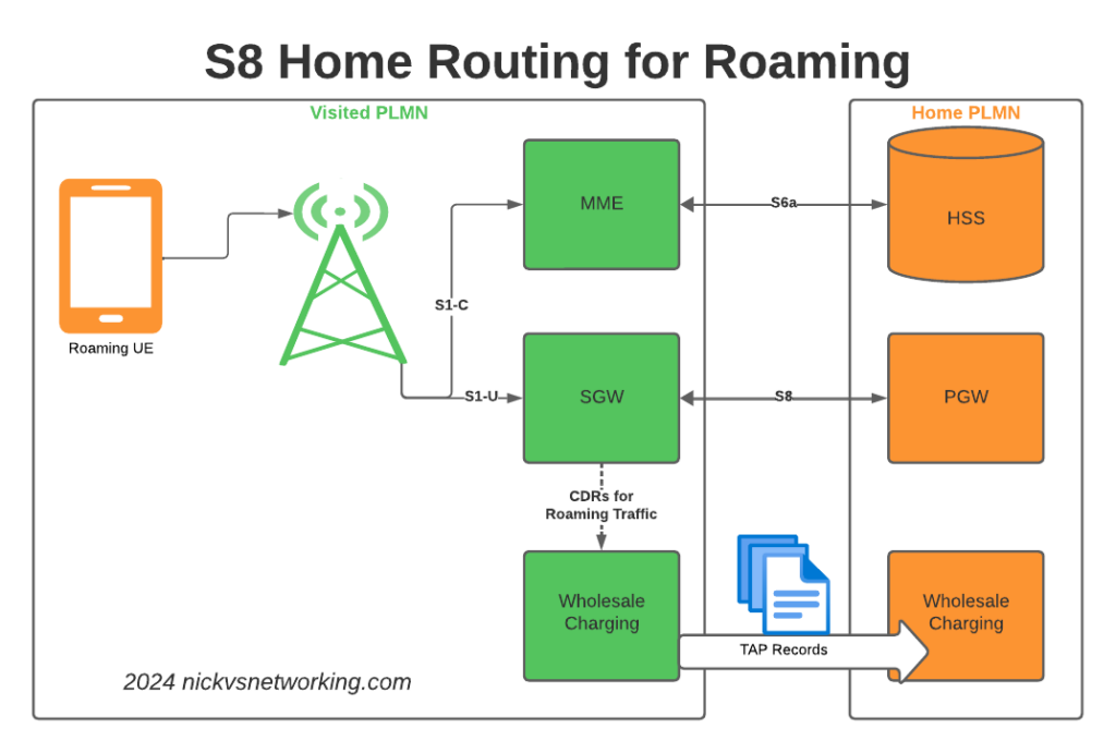
S8 Home Routing is a really simple concept, the traffic goes from the SGW in the visited PLMN to the PGW in the home PLMN, so the PCRF, OCS/OFCS, IMS, IP Addresses, etc, etc, are all in the home network, and this avoids huge amounts of complexity.
But in order for this to work, the visited network MME needs to find the PGW of the home network, and with over 700 roaming networks in commercial use, each one with potentially hundreds of unique APNs each routing to a different PGW, this is a tricky proposition.
If you’ve configured your PGW peers statically on your MME, that’s fine, but it doesn’t scale very well – And if you add an MVNO who wants their own PGW for serving their APN, well you’ll be adding some complexity there to, so what to do?
Well, the answer is DNS.
By taking the APN to be served, the home PLMN and the interface type desired, with some funky DNS queries, our MME can determine which PGW should be selected for a request.
Let’s take a look, for a UE from MNC XXX MCC YYY roaming into our network, trying to access the “IMS” APN.
Our MME knows the network code of the roaming subscriber from the IMSI is MNC XXX, MCC YYY, and that the UE is requesting the IMS APN.
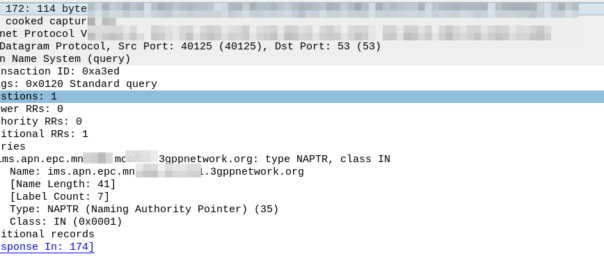
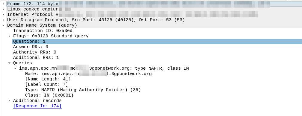
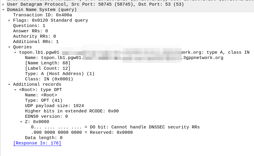
So our MME crafts a DNS request for the NAPTR query for ims.apn.epc.mncXXX.mccYYY.3gppnetwork.org:
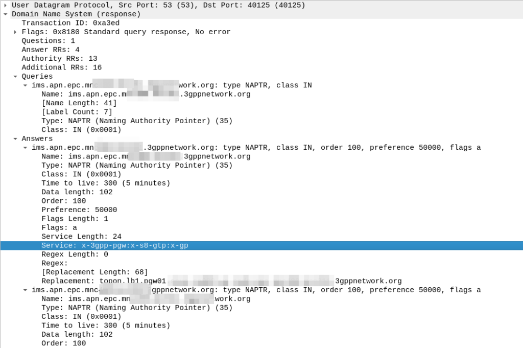
Because the domain is epc.mncXXX.mccYYY.3gppnetwork.org it’s routed to the authoritative DNS server in the home network, which sends back the response:
We’ve got a few peers to pick from, so we need to filter this list of Answers to only those that are relevant to us.
First we filter by the Service tag, whihc for each listed peer shows what services that peer supports.
But since we’re looking for S8, we need to find a peer who’s “Service” tag string contains:
x-3gpp-pgw:x-s8-gtp
We’re looking for two bits of info here, the presence of x-3gpp-pgw in the Service to indicate that this peer is a PGW and x-s8-gtp to indicate that this peer supports the S8 interface.
A service string like this:
x-3gpp-pgw:x-s5-gtp
Would be excluded as it only supports S5 not S8 (Even though they are largely the same interface, S8 is used in roaming).
It’s also not uncommon to see both services indicated as supported, in which case that peer could be selected too:
x-3gpp-pgw:x-s5-gtp:x-s8-gtp
(The answers in the screenshot include :x-gp which means the PGWs advertised are also co-located with a GGSN)
So with our answers whittled down to only those that meet our needs, we next use the Order and the Preference to pick our best candidate, this is the same as regular DNS selection logic.
From our candidate, we’ve also got the Regex Replacement, which allows our original DNS request to be re-written, which allows us to point at a single peer.
In our answer, we see the original request ims.apn.epc.mncXXX.mccYYY.3gppnetwork.org is to be re-written to topon.lb1.pgw01.epc.mncXXX.mccYYY.3gppnetwork.org.
This is the FQDN of the PGW we should use.
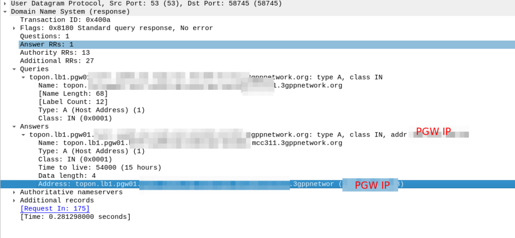
Now we know the FQND we should use, we just do an A-Record lookup (Or AAAA record lookup if it is IPv6) for that peer we are targeting, to turn that FQDN into an IP address we can use.
And then in comes the response:
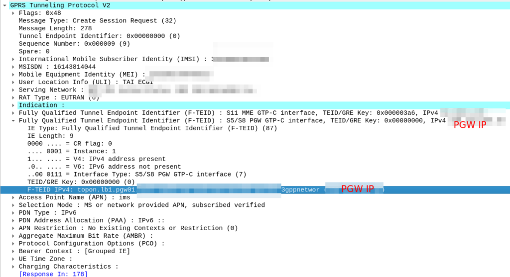
So now our MME knows the IP of the PGW, it can craft a Create Session request where the F-TEID for the S8 interface has the PGW IP set on it that we selected.
For more info on this TS 129.303 (Domain Name System Procedures) is the definitive doc, but the GSMA’s IR.88 “LTE and EPC Roaming Guidelines” provides a handy reference.
The S8 Home Routing approach for LTE Roaming works really well, as more and more operators are switching off their legacy circuit switched 2G/3G networks and shifting to LTE & VoLTE for roaming, we’re seeing more an more S8-HR deployments.
When LTE was being standardised in 2008, Local Breakout (LBO) and S8 Home Routing were both considered options for how roaming may look. Fast forward to today, and S8 Home routing is the only way roaming is done for modern deployments.
In light of this, there are some “best practices” in an “all S8 Home Routed” world, we’ve developed, that I thought I’d share.
The Basics
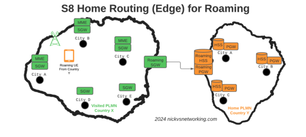
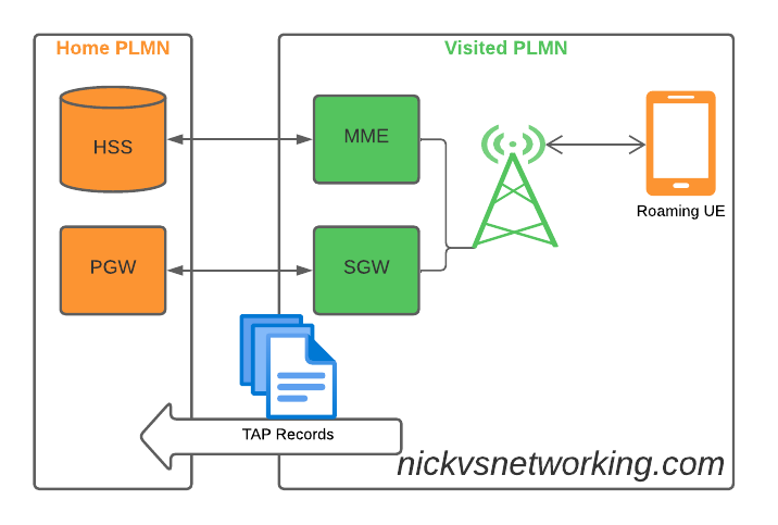
When roaming, the SGW in the Visited Network, sends user traffic back to the PGW in the Home Network.
This means Online/Offline charging, IMS, PCRF, etc, is all done in the Home PLMN. As long as data packets can get from the SGW in the Visited PLMN to the PGW in the Home PLMN, and authentication flows from the Visited MME to the HSS in the Home PLMN, you’re golden.
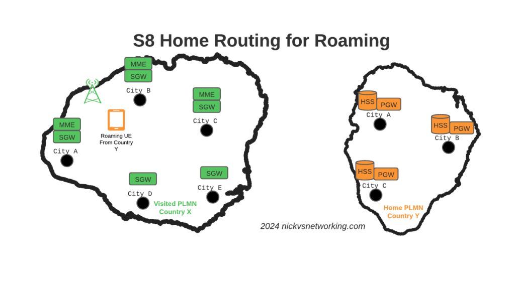
The Constraints
Of course real networks don’t look as simple as this, in reality a roaming scenario for a visited network has a lot more nodes, which need to be
Building Distributed Packet Core & IMS
Virtualization (VNF / CNF) has led operators away from “big iron” hardware for Packet Core & IMS nodes, towards software based solutions, which in turn offer a lot more flexibility.
Best practice for design of User Plane is to keep the the latency down, by bringing the user plane closer to the user (the idea of “Edge” UPFs in 5GC is a great example of this), and the move away from “big iron” in central locations for SGW and PGW nodes has been the trend for the past decade.
So to achieve these goals in the networks we build, we geographically distribute the core network.
This means we’ve got quite a few S-GW, P-GW, MME & HSS instances across the network. There’s some real advantages to this approach:
From a redundancy perspective this allows us to “spread the load” and build far more resilient networks. A network with 20 smaller HSS instances spread around the country, is far more resilient than 2 massive ones, regardless of how many power feeds or redundant disks it may have.
This allows us to be more resource efficient. MNOs have always provisioned excess capacity to cater for the loss of a node. If we have 2 MMEs serving a country, then each node has to have at least 50% capacity free, so if one MME were to fail, the other MME could handle the additional load it from it’s dead friend. This is costly for resources. Having 20 MMEs means each MME has to have 5% capacity free, to handle the loss of one MME in the pool.
It also forces our infrastructure teams to manage infrastructure “as cattle” rather than pets. These boxes don’t get names or lovingly crafted, they’re automatically spun up and destroyed without thinking about it.
For security, we only use internal IP addresses for the nodes in our packet core, this provides another layer of protection for the “crown jewels” of our network, so no one messing with BGP filtering can accidentally open the flood gates to our core, as one US operator learned leaving a GGSN open to the world leading to the private information for 100 million customers being leaked.
What this all adds to, is of course, the end user experience. For the end subscriber / customer, they get a better experience thanks to the reduced latency the connection provides, better uptime and faster call setup / SMS delivery, and less cost to deliver services.
I love this approach and could prothletise about it all day, but in a roaming context this presents some challenges.
The distributed networks we build are in a constant state of flux, new capacity is being provisioned in some areas, nodes things decommissioned in others, and our our core nodes are only reachable on internal IPs, so wouldn’t be reachable by roaming networks.
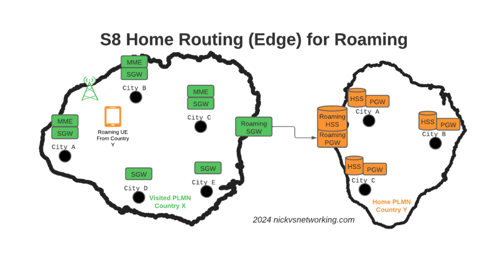
Our Distributed-Core Roaming Solution
To resolve this we’ve taken a novel approach, we’ve deployed a pair of S-GWs we call the “Roaming SGWs”, and a pair of P-GWs we call the “Roaming PGWs”, these do have public IPs, and are dedicated for use only by roaming traffic.
We really like this approach for a few reasons:
It allows us to be really flexible do what we want inside the network, without impacting roaming customers or operators who use our network for roaming. All the benefits I described from the distributed architectures can still be realised.
From a security standpoint, only these SGW/PGW pairs have public IPs, all the others are on internal IPs. This good for security – Our core network is the ‘crown jewels’ of the network and we only expose an edge to other providers. Even though IPX networks are supposed to be secure, one of the largest IPX providers had their systems breached for 5 years before it was detected, so being almost as distrustful of IPX traffic as Internet traffic is a good thing. This allows us to put these PGWs / SGWs at the “edge” of our network, and keep all our MMEs, as well as our on-net PGW and SGWs, on internal IPs, safe and secure inside our network.
For charging on the SGWs, we only need to worry about collecting CDRs from one set of SGWs (to go into the TAP files we use to bill the other operators), rather than running around hoovering up SGW CDRs from large numbers of Serving Gateways, which may get blown away and replaced without warning.
Of course, there is a latency angle to this, for international roaming, the traffic has to cross the sea / international borders to get to us. By putting it at the edge we’re seeing increased MOS on our calls, as the traffic is as close to the edge of the network as can be.
Caveat: Increased S11 Latency on Core Network sites over Satellite
This is probably not relevant to most operators, but some of our core network sites are fed only by satellite, and the move to this architecture shifted something: Rather than having latency on the S8 interface from the SGW to the PGW due to the satellite hop, we’ve got latency between the MME and the SGW due to the satellite hop.
It just shifts where in the chain the latency lies, but it did lead to us having to boost some timers in the MME and out of sequence deliver detection, on what had always been an internal interface previously.
Evolution to 5G Standalone Roaming
This approach aligns to the Home Routed options for 5G-SA roaming; UPF chaining means that the roaming traffic can still be routed, as seems to be the way the industry is going.
SA roaming is in its infancy, without widely deployed SA networks, we’re not going to see common roaming using SA for a good long while, but I’ll be curious to see if this approach becomes the de facto standard going forward.
Where to from here?
We’re pretty happy with this approach in the networks we’ve been building.
So far it’s made IREG testing easier as we’ve got two fixed points the IPX needs to hit (The DRAs and the SGWs) rather than a wide range of networks.
Operators with a vast number of APNs they need to drop into different VRFs may have to do some traffic engineering here – Our operations are generally pretty flat, but I can see where this may present some challenges for established operators shifting their traffic.
I’d be keen to hear if other operators are taking this approach and if they’ve run into any issues, or any issues others can see in this, feel free to drop a comment below.
I got an email the other day asking a simple question:
How do I know if a subscriber is VoLTE roaming or not when they send an SMS to charge for it?
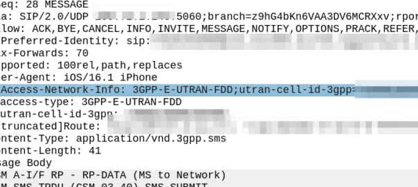
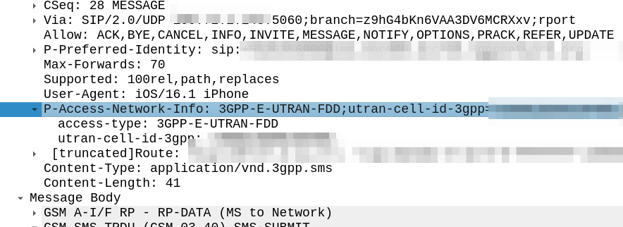
My immediate reaction was to look at the SIP headers, P-Access-Network-Info will tell you where the subscriber is located, end of.
Right?
Well not quite, this will tell the SMSc the location of the subscriber sending the SMS. If the PLMN in the P-Access-Network-Info != the home PLMN, the sub is roaming.
But does this information get passed to the OCS / OFCS?
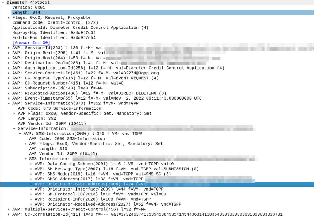
The SMSc uses “Event based charging” to perform credit control, so let’s have a look at what AVPs are present in the Credit Control Request from the SMSc:
Hmm, the SMS-Information AVP (2000) contains a bunch of information about the SMS being sent, but I don’t see anything about the location of the sender in there.
Originator-Interface is just set to “SIP”, of course in a 2G/3G roaming scenario the Originator-SCCP-Address would be that of the Visited PLMN, but for us it is our SCCP address.
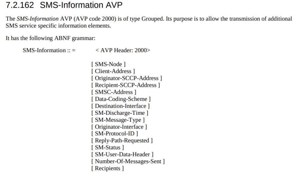
Maybe the standard allows for an additional optional AVP in the SMS-Information-AVP we’re missing? Let’s check TS 32.299:
Nope.
So how to deal with this?
While the standards aren’t totally clear on this, we added an IMS-Info AVP and inside that populated the Access-Network-Information directly from the SIP header, and then picked that off inside our OCS in order to apply the correct rules.
If you’ve ever worked in roaming, you’ll probably have had the misfortune of dealing with Transferred Account Procedures aka TAP files.
It’s used for billing a 2G GSM call right up to 5G data usage, if you use a service while roaming, somewhere in the world there’s a TAP file with your usage in it.
A brief history of TAP
TAP was originally specified by the GSMA in 1991 as a standard CDR interchange format between operators, for use in roaming scenarios.
Notice I said GSMA – Not 3GPP – This means there’s no 3GPP TS docs for this, it’s defined by the industry lobby group’s members, rather than the standards body.
So what does this actually mean? Well, if you’re MNO A and a customer from MNO B roams into your network, all the calls, SMS and data consumed by the roaming subscriber from MNO B will need to be billed to MNO B, by you, MNO A.
If a network operator wants to get paid for traffic used on their network by roaming subscribers, they’d better send out a TAP file to the roamer’s home network.
TAP is the file format generated my MNO A and sent to MNO B, containing all the usage charges that subscribers from MNO B have racked up while roaming into your network.
These are broken down into “Transactions” (CDRs), for events like making a call, connecting a PDN session and consuming data, or sending a text.
In the beginning of time, GSM provided only voice calling service. This meant that the only services a subscriber could consume while roaming was just making/receiving voice calls which were billed at the end of each month. – This meant billing was equally simple, every so often the visisted network would send the TAP files for the voice calls made by subscribers visited other networks, to the home networks, which would markup those charges, and add them onto the monthly invoice for each subscriber who was roaming.
But of course today, calling accounts for a tiny amount of usage on the network, but this happened gradually while passing through the introduction of SMS, CAMEL services, prepaid services, mobile data, etc. For all these services that could be offered, the TAP format had to evolve to handle each of these scenarios.
As we move towards a flat IP architecture, where voice calls and SMS sent while roaming are just data, TAP files for 4G and 5G networks only need to show data transactions, so the call objects, CAMEL parameters and SMS objects are all falling by the wayside.
What’s inside a TAP File
TAP uses the most beloved of formats – ASN1 to encode the data. This means it is strictly formatted and rigidly specified.
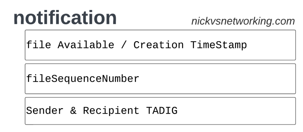
Each file contains a Sequence Number which is a monotonically increasing number, which allows the receiver to know if any files have been missed between the file that’s being currently parsed, an the previous file.
They also have a recipient and sender TADIG code, which is a code allocated by GSMA that uniquely identifies the sender and the recipient of the file.
The TAP records exist in one of two common format, Notification Records and transferBatch records.
These files are exchanged between operators, in practice this means “Dumped on an FTP server as agreed between the two”.
TAP Notification Records
Notifications are the simplest of TAP records and are used when there aren’t any CDRs for roaming events during the time period the TAP file covers.
These are essentially blank TAP files generated by the visited network to let the home network know it’s still there, but there are no roaming subs consuming services in that period.
Notification files are really simple, let’s take a look as one shown as JSON:
When we have services to bill and records to charge, that’s when instead we generate a transferBatch record.
It looks something like this:
There’s a lot going on in here, so let’s break it down section by section.
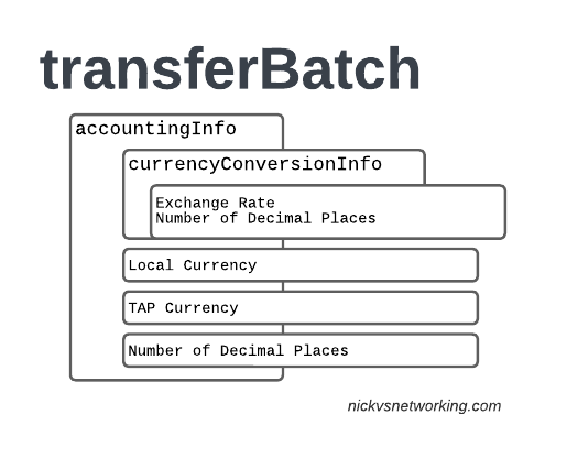
accountingInfo
The accountingInfo section specifies the currency, exchange rate parameters.
Keep in mind a TAP record generated by an operator in the US, would use USD, while the receiver of the file may be a European MNO dealing in EUR.
This gets even more complicated if you’re dealing with more obscure currencies where an intermediary currency is used, that’s where we bring in SDRs (“Special Drawing Right”) that map to the dollar value to be charged, kinda – the roaming agreement defines how many SDRs are in a dollar, in the example below we’re not using any, but you do see it.
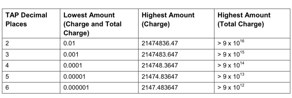
When it comes to numbers and decimal places, TAP doesn’t exactly make it easy.
Significant Digits are defined by counting the first number before the decimal point and all the numbers to the right of the decimal point, so for example the number 1.234 would be 4 significant digits (1 digit before the decimal point and 3 digits after it).
Decimal Places are not actually supported for the Value fields in the TAP file. This is tricky because especially today when roaming tariffs are quite low, these values can be quite small, and we need to represent them as an integer number. TAP defines decimal places as the number of digits after the decimal place.
When it comes to the maximum number of decimal places, this actually impacts the maximum number we can store in the field – as ASN1 strictly enforce what we put in it.
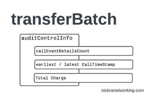
The auditControlInfo section contains the number of CDRs (callEventDetailsCount) contained in the TAP file, the timestamp of the first and last CDR in the file, the total charge and any tax charged.
All of the currency information was provided in the accountingInfo so this is just giving us our totals.
A CDR has 30 days from the time it was generated / service consumed by the roamer, to be baked into a TAP file. After this we can no longer charge for it, so it’s important that the earliestCallTimeStamp is not more than 30 days before the fileCreationTimeStamp seen in batchControlInfo.
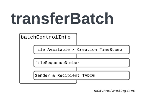
batchControlInfo
The batchControlInfo section specifies the time the TAP file became available for transfer, the time the file was created (usually the same), the sequence number and the sender / recipient TADIG codes.
As mentioned earlier, we track sequence number so the receiver can know if a TAP file has been missed; for example if you’ve got TAP file 1 and TAP file 3 comes in, you can determine you’ve missed TAP file 2.
Now we’re getting to the meat & potatoes of our TAP record, the CDRs themselves.
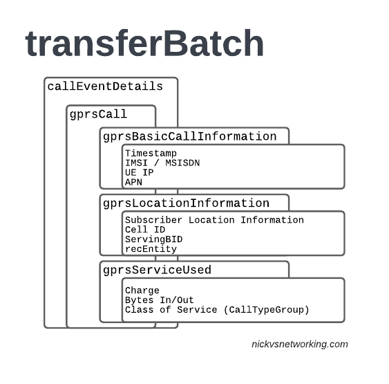
In LTE networks these are just records of data consumption, so let’s take a look inside the gprsCall records under callEventDetails:
In the gprsBasicCallInformation we’ve got as the name suggests the basic info about the data usage event. The time when the session started, the charging ID, the IMSI and the MSISDN of the subscriber to charge, along with their IP and the APN used.
Next up we have the gprsLocationInformation – rates and tariffs may be set based on the location of the subscriber, so we need to identify the area the sub was using the services to select correct tariff / rate for traffic in this destination.
The recEntity is the index number of the SGW / PGW used for the transaction (more on that later).
Next we have the gprsServiceUsed which, again as the name suggests, details the services used and the charge.
chargeDetailList contains the charged data (Made up of dataVolumeIncoming + dataVolumeOutgoing) and the cost.
The chargeableUnits indicates the actual data consumed, however most roaming agreements will standardise on some level of rounding, for example rounding up to the nearest Kilobyte (1024 bytes), so while a sub may consume 1025 bytes of data, they’d be billed for 2045 bytes of data. The data consumed is indicated in the chargeableUnits which indicates how much data was actually consumed, before any rounding policies where applied, while the amount that is actually charged (When taking into account rounding policies) isindicated inside Charged Units.
In the example below data usage is rounded up to the nearest 1024 bytes, 134390 bytes rounds up to the nearest 1024 gives you 135168 bytes.
As this is data we’re talking bytes, but not all bytes are created equal!
VoLTE traffic, using a QCI1 bearer is more valuable than QCI 9 cat videos, and TAP records take this into account in the Call Type Groups, each of which has a different price – Call Type Level 1 indicates the type of traffic, for S8 Home Routed LTE Traffic this is 10 (HGGSN/HP-GW), while Call Type Level 2 indicates the type of traffic as mapped to QCI values:
So Call Type Level 2 set to 20 indicates that this is “20 Unspecified/default LTE QCIs”, and Call Type Level 3 can be set to any value based on a defined inter-operator tariff.
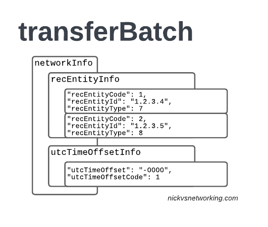
recEntityType 7 means a PGW and contains the IP of the PGW in the Home PLMN, while recEntityType 8 means SGW and is the SGW in the Visited PLMN.
So this means if we reference recEntityCode 2 in a gprsCall, that we’re referring to an SGW at 1.2.3.5.
Lastly also got the utcTimeOffsetInfo to indicate the timezones used and assign a unique code to it.
Using the Records
We as humans? These records aren’t meant for us.
They’re designed to be generated by the Visited PLMN and sent to to the home PLMN, which ingests it and pays the amount specified in the time agreed.
Generally this is an FTP server that the TAP records get dumped into, and an automated bank transfer job based on the totals for the TAP records.
Testing of the TAP records is called “TADIG Testing” and it’s something we’ll go into another day, but in essence it’s validating that the output and contents of the files meet what both operators think is the contract pricing and specifications.
So that’s it! That’s what’s in a TAP record, what it does and how we use it!
GSMA are introducing BCE – Billing & Charging Evolution, a new standard, designed to last for the next 30+ years like TAP has. It’s still in its early days, but that’s the direction the GSMA has indicated it would like to go.