Monthly Archives: May 2023

Huawei BBU 3900 Architecture

Huawei BTS3900 eNB Configuration

Last year I purchased a cheap second hand Huawei macro base station – there’s lots of these on the market at the moment due to the fact they’re being replaced in many countries.

I’m using it in my lab environment, and as such the config I’ve got is very “bare bones” and basic. Keep in mind if you’re looking to deploy a Macro eNodeB in production, you may need more than just a blog post to get everything tuned and functioning properly…

In this post we’ll cover setting up a Huawei BTS3900 eNodeB from scratch, using the MML interface, without relying on the U2020 management tool.

Obviously the details I setup (IP Addressing, PLMN and RF parameters) are going to be different to what you’re configuring, so keep that in mind, where I’ve got my MME Addresses, site IDs, TACs, IP Addresses, RFUs, etc, you’ll need to substitute your own values.

A word on Cabinets

Typically these eNodeBs are shipped in cabinets, that contain the power supplies, alarm / environmental monitoring, power distribution, etc.

Early on in the setup process we’ll be setting the cabinet types we’ve got, and then later on we’ll tell the system what we have installed in which slots.

This is fine if you have a cabinet and know the type, but in my case at least I don’t have a cabinet manufactured by Huawei, just a rack with some kit mounted in it.

This is OK, but it leads to a few gotchas I need to add a cabinet (even though it doesn’t physically exist) and when I setup my RRUs I need to define what cabinet, slot and subrack it’s in, even though it isn’t in any. Keep this in mind as we go along and define the position of the equipment, that if you’re not using a real-world cabinet, the values mean nothing, but need to be kept consistent.

The Basics

Before we get started, familiarise yourself with the Huawei MML we’ll use for configuring the unit, and log into the Web UI and bring up an MML shell.

To begin we’ll need to setup the basics, by disabling DHCP and setting an local IP Address for the unit.

 SET DHCPSW: SWITCH=DISABLE;
 SET LOCALIP: IP="192.168.5.234", MASK="255.255.248.0";

Obviously your IP address details will be different.
Next we’ll add an eNodeB function, the LMPT / UMPT can have multiple functions and multiple eNodeBs hosted on the same hardware, but in our case we’re just going to configure one:

 ADD ENODEBFUNCTION: eNodeBFunctionName="LTE", ApplicationRef=1, eNodeBId=9527;
 SET NE: NENAME="HUAWEI", LOCATION="NewSite", DID="NewSite12345", SITENAME="NewSite1", USERLABEL="NewInitSite";
 ADD LOCATION: LOCATIONNAME="NewSite", GCDF=Degree, LATITUDEDEGFORMAT=0, LONGITUDEDEGFORMAT=0; 

Again, your eNodeB ID, location, site name, etc, are all going to be different, as will your location.

Next we’ll set the system to maintenance mode (MNTMODE), so we can make changes on the fly (this takes the eNB off the air, but we’re already off the air), you’ll need to adjust the start and end times to reflect the current time for the start time, and end time to be after you’re done setting all this up.

 SET MNTMODE: MNTMode=INSTALL, ST=2013&09&20&15&00&00, ET=2013&09&25&15&00&00, MMSetRemark="NewSite Install";

Next we’ll set the operator details, this is the PLMN of the eNodeB, and create a new tracking area.

 ADD CNOPERATOR: CnOperatorId=0, CnOperatorName="NickTest", CnOperatorType=CNOPERATOR_PRIMARY, Mcc="001", Mnc="01";
ADD CNOPERATORTA: TrackingAreaId=0, CnOperatorId=0, Tac=1;

Next we’ll be setting and populating the cabinets I mentioned earlier. I’ll be telling the unit it’s inside a APM30 (Cabinet 0), and in Cabinet Number 0, Subrack 0, is a BBU3900.

 //To modify the cabinet type, run the following command:
ADD CABINET:CN=0,TYPE=APM30;
//Add a BBU3900 subrack, run the following command:
ADD SUBRACK:CN=0,SRN=0,TYPE=BBU3900;
//To configure boards and RF datas, run the following commands:

And inside the BBU3900 there’s some cards of course, and each card has as slot, as per the drawing below.

In my environment I’ve got a LMPT in slot 7, and a LBBP in Slot 3. There’s a fan and a UPEU too, so:
We’ll add a board in Slot No. 7, of type LMPT,
We’ll add a board in Slot No. 3, of type LBBP working on FDD,
We’ll add a fan board in Slot No. 16, and a UPEU in Slot No. 18.

 ADD BRD:SN=7,BT=LMPT;
 ADD BRD:CN=0,SRN=0,SN=3,BT=LBBP,WM=TDD;
 ADD BRD:CN=0,SRN=0,SN=16,BT=FAN;
 ADD BRD:CN=0,SRN=0,SN=18,BT=UPEU;

Huawei publish design guides for which cards should be in which slots, the general rule is that your LMPT / UMPT card goes in Slot 7, with your BBP cards (UBBP or LBBP) in slots 3, then 2, then 1, then 0. Fans and UPEUs can only go in the slots designed to fit them, so that makes it a bit easier.

Next we’ll need to setup our RRUs, for this we’ll need to setup an RRU chain, which is the Huawei term for the CPRI links and add an RRU into it:

ADD RRUCHAIN:RCN=10,TT=CHAIN,BM=COLD,HSRN=70,HSN=0,HPN=0;

ADD RRU:CN=0,SRN=60,SN=0,TP=BRANCH,RCN=10,PS=0,RT=MPMU,RS=TDL,RXNUM=0,TXNUM=0;

With our RRU chains defined, we’ll need to setup our transport network to get the traffic back to the S-GW / MME:

SET ETHPORT: SN=7, SBT=BASE_BOARD, PA=COPPER, SPEED=AUTO, DUPLEX=AUTO;
ADD DEVIP: SN=7, SBT=BASE_BOARD, PT=ETH, PN=0, IP="10.10.10.67", MASK="255.255.255.0";
ADD IPRT: RTIDX=0, SN=7, SBT=BASE_BOARD, DSTIP="10.166.1.251", DSTMASK="255.255.255.255", RTTYPE=NEXTHOP, NEXTHOP="10.10.10.1"; 
ADD IPRT: RTIDX=1, SN=7, SBT=BASE_BOARD, DSTIP="10.4.3.3", DSTMASK="255.255.255.255", RTTYPE=NEXTHOP, NEXTHOP="10.10.10.1"; 
ADD IPRT: RTIDX=2, SN=7, SBT=BASE_BOARD, DSTIP="10.3.3.3", DSTMASK="255.255.255.255", RTTYPE=NEXTHOP, NEXTHOP="10.10.10.1";
ADD IPRT: RTIDX=3, SN=7, SBT=BASE_BOARD, DSTIP="10.60.60.60", DSTMASK="255.255.255.255", RTTYPE=NEXTHOP, NEXTHOP="10.10.10.1";
ADD OMCH: IP="10.10.10.67", MASK="255.255.255.0", PEERIP="10.166.1.251", PEERMASK="255.255.255.255", BEAR=IPV4, BRT=YES, RTIDX=0, BINDSECONDARYRT=NO, CHECKTYPE=NONE;
ADD VLANMAP: NEXTHOPIP="10.10.10.1", MASK="255.255.248.0", VLANMODE=SINGLEVLAN, VLANID=3721, SETPRIO=DISABLE; 
ADD SCTPTEMPLATE: SCTPTEMPLATEID=0, SWITCHBACKFLAG=ENABLE;
ADD SCTPHOST: SCTPHOSTID=0, IPVERSION=IPv4, SIGIP1V4="10.10.10.67", SIGIP1SECSWITCH=DISABLE, SIGIP2SECSWITCH=DISABLE, PN=2000, SCTPTEMPLATEID=0;
ADD SCTPPEER: SCTPPEERID=0, IPVERSION=IPv4, SIGIP1V4="10.3.3.3", SIGIP1SECSWITCH=DISABLE, SIGIP2SECSWITCH=DISABLE, PN=2000;
ADD USERPLANEHOST: UPHOSTID=0, IPVERSION=IPv4, LOCIPV4="10.10.10.67", IPSECSWITCH=DISABLE;
ADD EPGROUP: EPGROUPID=0;
ADD SCTPHOST2EPGRP: EPGROUPID=0, SCTPHOSTID=0; 
ADD SCTPPEER2EPGRP: EPGROUPID=0, SCTPPEERID=0;
ADD UPHOST2EPGRP: EPGROUPID=0, UPHOSTID=0;
ADD S1: S1Id=0, CnOperatorId=0, EpGroupCfgFlag=CP_UP_CFG, CpEpGroupId=0, UpEpGroupId=0;


We’ll need clocking and time as well, we’ll use NTP and GPS:

SET TIMESRC: TIMESRC=NTP; 
ADD NTPC: MODE=IPV4, IP="10.166.1.251", PORT=123, SYNCCYCLE=60, AUTHMODE=PLAIN; 
SET MASTERNTPS: MODE=IPV4, IP="10.166.1.251"; 
SET TZ: ZONET=GMT+0800, DST=NO;

ADD GPS: SRN=0, SN=7;
SET CLKMODE: MODE=MANUAL, CLKSRC=GPS, SRCNO=0;
SET CLKSYNCMODE:CLKSYNCMODE=TIME;

Next we’ll need to define a sector, sector equipment & cell, then link it to a sector equipment group:

ADD SECTOR:SECTORID=0,ANTNUM=2,ANT1CN=0,ANT1SRN=60,ANT1SN=255, ANT1N=R0A,ANT2CN=0,ANT2SRN=60,ANT2SN=255,ANT2N=R0B,CREATESECTOREQM=FALSE;

ADD SECTOREQM:SECTOREQMID=0,SECTORID=0,ANTNUM=2,ANT1CN=0, ANT1SRN=60,ANT1SN=255,ANT1N=R0A,ANTTYPE1=RXTX_MODE,ANT2CN=0,ANT2SRN=60,ANT2SN=255,ANT2N=R0B,ANTTYPE2=RXTX_MODE;

ADD CELL:LOCALCELLID=1,CELLNAME="CELL1",FREQBAND=41,ULEARFCNCFGIND=NOT_CFG,DLEARFCN=40340,ULBANDWIDTH=CELL_BW_N100,DLBANDWIDTH=CELL_BW_N100,CELLID=1,PHYCELLID=1,FDDTDDIND=CELL_TDD,SUBFRAMEASSIGNMENT=SA2,SPECIALSUBFRAMEPATTERNS=SSP5,ROOTSEQUENCEIDX=0,CUSTOMIZEDBANDWIDTHCFGIND=NOT_CFG,EMERGENCYAREAIDCFGIND=NOT_CFG,UEPOWERMAXCFGIND=NOT_CFG,MULTIRRUCELLFLAG=BOOLEAN_TRUE,MULTIRRUCELLMODE=MPRU_AGGREGATION, CPRICOMPRESSION=NORMAL_COMPRESSION,TXRXMODE=2T2R;

ADD EUSECTOREQMGROUP:LOCALCELLID=1,SECTOREQMGROUPID=1;
ADD EUSECTOREQMID2GROUP:LOCALCELLID=1,SECTOREQMGROUPID=1, SECTOREQMID=0;

Alright, now we can activate it:

//Modify the reference signal power.
MOD PDSCHCFG: LocalCellId=1, ReferenceSignalPwr=-81;

//Add an operator for the cell.
ADD CELLOP: LocalCellId=0, TrackingAreaId=0;

//Activate the cell.
ACT CELL: LocalCellId=1;

And lastly we can define some neighboring cells:

//Configure neighboring cells. 
ADD EUTRANINTERNFREQ: LocalCellId=1, DlEarfcn=3100, UlEarfcnCfgInd=NOT_CFG, CellReselPriorityCfgInd=NOT_CFG, SpeedDependSPCfgInd=NOT_CFG, MeasBandWidth=MBW100, PmaxCfgInd=NOT_CFG, QqualMinCfgInd=NOT_CFG;
ADD EUTRANEXTERNALCELL: Mcc="460", Mnc="02", eNodeBId=236, CellId=0, DlEarfcn=3100, UlEarfcnCfgInd=NOT_CFG, PhyCellId=236, Tac=33;
ADD EUTRANINTERFREQNCELL: LocalCellId=1, Mcc="460", Mnc="02", eNodeBId=236, CellId=0;

BSF Addresses

The Binding Support Function is used in 4G and 5G networks to allow applications to authenticate against the network, it’s what we use to authenticate for XCAP and for an Entitlement Server.

Rather irritatingly, there are two BSF addresses in use:

If the ISIM is used for bootstrapping the FQDN to use is:

bsf.ims.mncXXX.mccYYY.pub.3gppnetwork.org

But if the USIM is used for bootstrapping the FQDN is

bsf.mncXXX.mccYYY.pub.3gppnetwork.org

You can override this by setting the 6FDA EF_GBANL (GBA NAF List) on the USIM or equivalent on the ISIM, however not all devices honour this from my testing.

Will 5GC be used in Wireline Access? No. Here’s why.

One of the hyped benefits of a 5G Core Networks is that 5GC can be used for wired networks (think DSL or GPON) – In marketing terms this is called “Wireless Wireline Convergence” (5G WWC) meaning DSL operators, cable operators and fibre network operators can all get in on this sweet 5GC action and use this sexy 5G Core Network tech.

This is something that’s in the standards, and that the big kit vendors are pushing heavily in their marketing materials. But will it take off? And should operators of wireline networks (fixed networks) be looking to embrace 5GC?

Comparing 5GC with current wireline network technologies isn’t comparing apples to apples, it’s apples to oranges, and they’re different fruits.

At its heart, the 3GPP Core Networks (including 5G Core) address one particular use cases of the cellular industry: Subscriber mobility – Allowing a customer to move around the network, being served by different kit (gNodeBs) while keeping the same IP Address.

The most important function of 5GC is subscriber mobility.

This is achieved through the use of encapsulating all the subscriber’s IP data into a GTP (A protocol that’s been around since 2G first added data).

Do I need a 5GC for my Fixed Network?

Wireline networks are fixed. Subscribers don’t constantly move around the network. A GPON customer doesn’t need to move their OLT every 30 minutes to a new location.

Encapsulating a fixed subscriber’s traffic in GTP adds significant processing overhead, for almost no gain – The needs of a wireline network operator, are vastly different to the needs of a cellular core.

Today, you can take a /24 IPv4 block, route it to a DSLAM, OLT or CMTS, and give an IP to 254 customers – No cellular core needed, just a router and your access device and you’re done, and this has been possible for decades.
Because there’s no mobility the GTP encapsulation that is the bedrock for cellular, is not needed.

Rather than routing directly to Access Network kit, most fixed operators deploy BRAS systems used for fixed access. Like the cellular packet core, BRAS has been around for a very long time, with a massive install base and a sea of engineering experience in house, it meets the needs of the wireline industry who define its functions and roles along with kit vendors of wireline kit; the fixed industry working groups defined the BRAS in the same way the 3GPP and cellular industry working groups defined 5G Core.

I don’t forsee that we’ll see large scale replacement of BRAS by 5GC, for the same reason a wireless operator won’t replace their mobile core with a BRAS and PPPoE – They’re designed to meet different needs.

All the other features that have been added to the 3GPP Core Network functionality, like limiting speed, guaranteed throughput bearers, 5QI / QCI values, etc, are addons – nice-to-haves. All of these capabilities could be implemented in wireline networks today – if the business case and customer demand was there.

But what about slicing?

With dropping ARPUs across the board, additional services relating to QoS (“Network Slicing”) are being held up as the saving grace of revenues for cellular operators and 5G as a whole, however this has yet to be realized and early indications suggest this is not going to be anywhere near as lucrative as previously hoped.

What about cost savings?

In terms of cost-per-bit of throughput, the existing install base wireline operators have of heavy-metal kit capable of terabit switching and routing has been around for some time in fixed world, and is what most 5G Cores will connect to as their upstream anyway, so there won’t be any significant savings on equipment, power consumption or footprint to be gained.

Fixed networks transport the majority of the world’s data today – Wireline access still accounts for the majority of traffic volumes, so wireline kit handles a higher magnitude of throughput than it’s Packet Core / 5GC cousins already.

Cutting down the number of parts in the network is good though right?

If you’re operating both a Packet Core for Cellular, and a fixed network today, then you might think if you moved from the traditional BRAS architecture fore the wired network to 5GC, you could drop all those pesky routers and switches clogging up your CO, Exchanges and Data Centers.

The problem is that you still need all of those after the 5GC to be able to get the traffic anywhere users want to go. So the 5GC will still need all of that kit, all your border routers and peering routers will remain unchanged, as well as domestic transmission, MPLS and transport.

The parts required for operating fixed networks is actually pretty darn small in comparison to that of 5GC.

TL;DR?

While cellular vendors would love to sell their 5GC platform into fixed operators, the premise that they are willing to replace existing BRAS architectures with 5GC, is as unlikely in my view as 5GC being replaced by BRAS.

Tiny Pillars in the CAN

On the rare occasions I’m not tied to my desk, I’m out for a long run along some back roads somewhere.

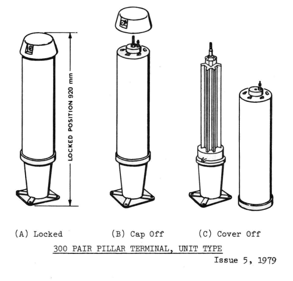
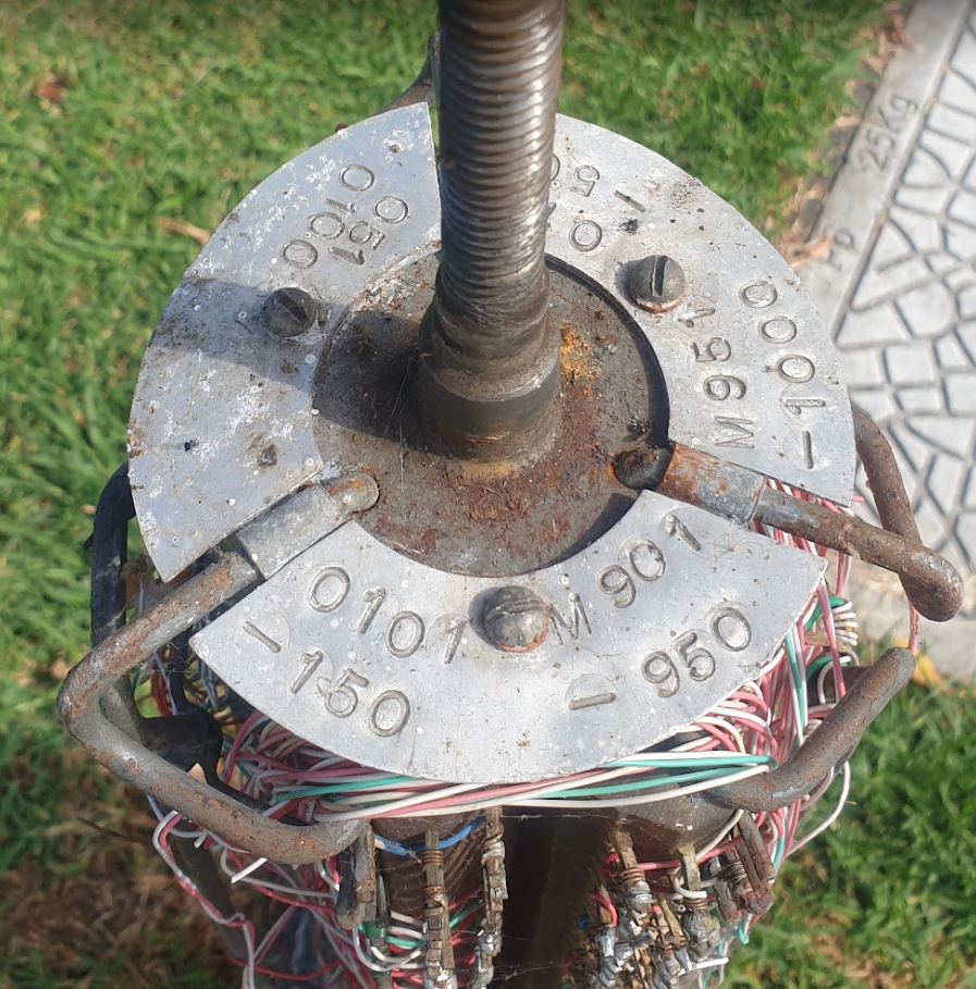
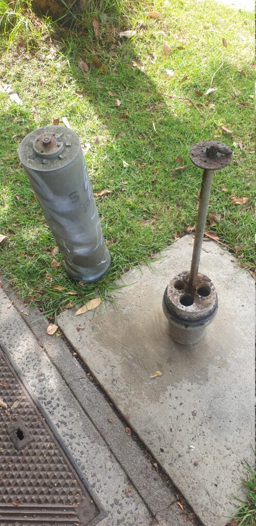
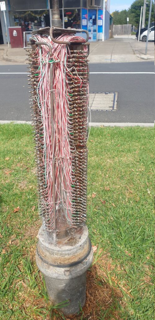
Every now and then I come across these tiny telecom pillars for cross-connection (and don’t shoot at them) – I mostly find them around the edges of distribution areas.
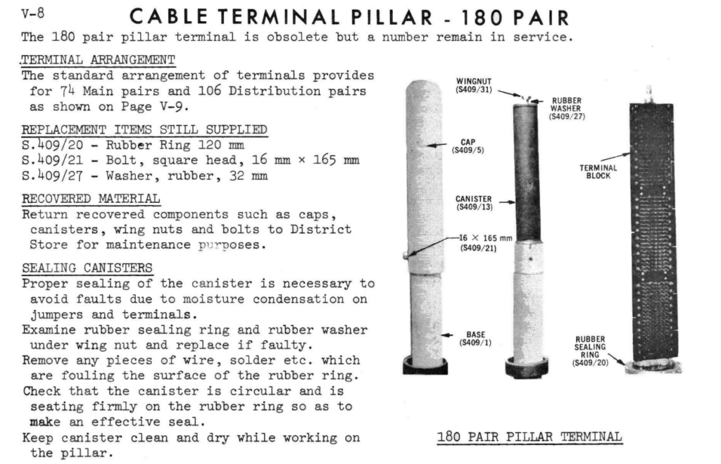
I had some recollection that these were originally for trunk lines between exchanges (maybe there was some truth to this?), but some digging in old docs show these were just for interconnecting main or branch cables with distribution cables, in areas where the 600 and 1200 pair pillars / cabinets would be overkill.

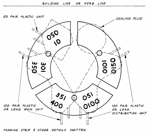
They’re built like the 900/1800 pair cabinets, but just scaled down versions, supporting 1x 100 pair main cable, 1x 100 pair distribution cables and 2x 50 pair distribution cables.

It seems like these were largely decomed when NBN took over, leaving most with a big X sprayed on them.

While I was looking through the docs I also found reference to a 180 pair pillar, which looked very similar, but I’ve yet to see any of them left in the wild. Better keep running ’till I find one!

Authenticating Fixed Line Subscribers into IMS

We recently added support in PyHSS for fixed line SIP subscribers to attach to the IMS.

Traditional telecom operators are finding their fixed line network to be a bit of a money pit, something they’re required to keep operating to meet regulatory obligations, but the switches are sitting idle 99% of the time. As such we’re seeing more and more operators move fixed line subs onto their IMS.

This new feature means we can use PyHSS to serve as the brains for a fixed network, as well as for mobile, but there’s one catch – How we authenticate subscribers changes.

Most banks of line cards in a legacy telecom switches, or IP Phones, don’t have SIM slots to allow us to authenticate, so instead we’re forced to fallback to what they do support.

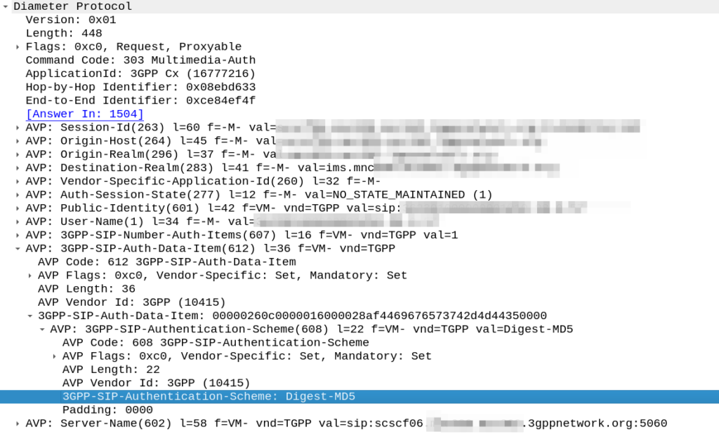
Unfortunately for the most part, what is supported by these IP phones or telecom switches is SIP MD5 Digest Authentication.

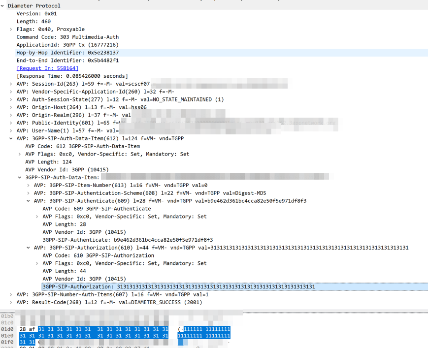
The Nonce is generated by the HSS and put into the Multimedia-Authentication-Answer, along with the subscriber’s password and sent in the clear to the S-CSCF.

Subscriber with Password made up of all 1's MAA response from HSS for Digest-MD5 Auth

The HSS then generates the the Multimedia-Auth Answer, it generates a nonce (in the 3GPP-SIP-Authenticate / 609 AVP) and sends the Subscriber’s password in the 3GPP-SIP-Authorization (610) AVP in response back to the S-CSCF.

I would have thought a better option would be for the HSS to generate the Nonce and Digest, and then the S-CSCF to just send the Nonce to the Sub and compare the returned Digest from the Sub against the expected Digest from the HSS, but it would limit flexibility (realm adaptation, etc) I guess.

The UE/UA (I guess it’s a UA in this context as it’s not a mobile) then generates its own Digest from the Nonce and sends it back to the S-CSCF via the P-CSCF.

The S-CSCF compares the received Digest response against the one it generated, and if the two match, the sub is authenticated and allowed to attach onto the network.