Monthly Archives: October 2021

Demystifying SS7 & Sigtran – Part 3 – SS7 Lab in GNS3

This is part of a series of posts looking into SS7 and Sigtran networks. We cover some basic theory and then get into the weeds with GNS3 based labs where we will build real SS7/Sigtran based networks and use them to carry traffic.

So we’ve made it through the first two parts of this series talking about how it all works, but now dear reader, we build an SS7 Lab!

At one point, and SS7 Signaling Transfer Point would be made up of at least 3 full size racks, and cost $5M USD.
We can run a dozen of them inside GNS3!


This post won’t cover usage of GNS3 itself, there’s plenty of good documentation on using GNS3 if you need to get acquainted with it before we start.

Cisco’s “IP Transfer Point” (ITP) software adds SS7 STP functionality to some models of Cisco Router, like the 2651XM and C7200 series hardware.

Luckily for us, these hardware platforms can be emulated in GNS3, so that’s how we’ll be setting up our instances of Cisco’s ITP product to use as STPs in our network.

For the rest of this post series, I’ll refer to Cisco’s IP Transfer Point as the “Cisco STP”.

Not open source you say! Osmocom have OsmoSTP, which we’ll introduce in a future post, and elaborate on why later…

From inside GNS3, we’ll create a new template as per the Gif below.
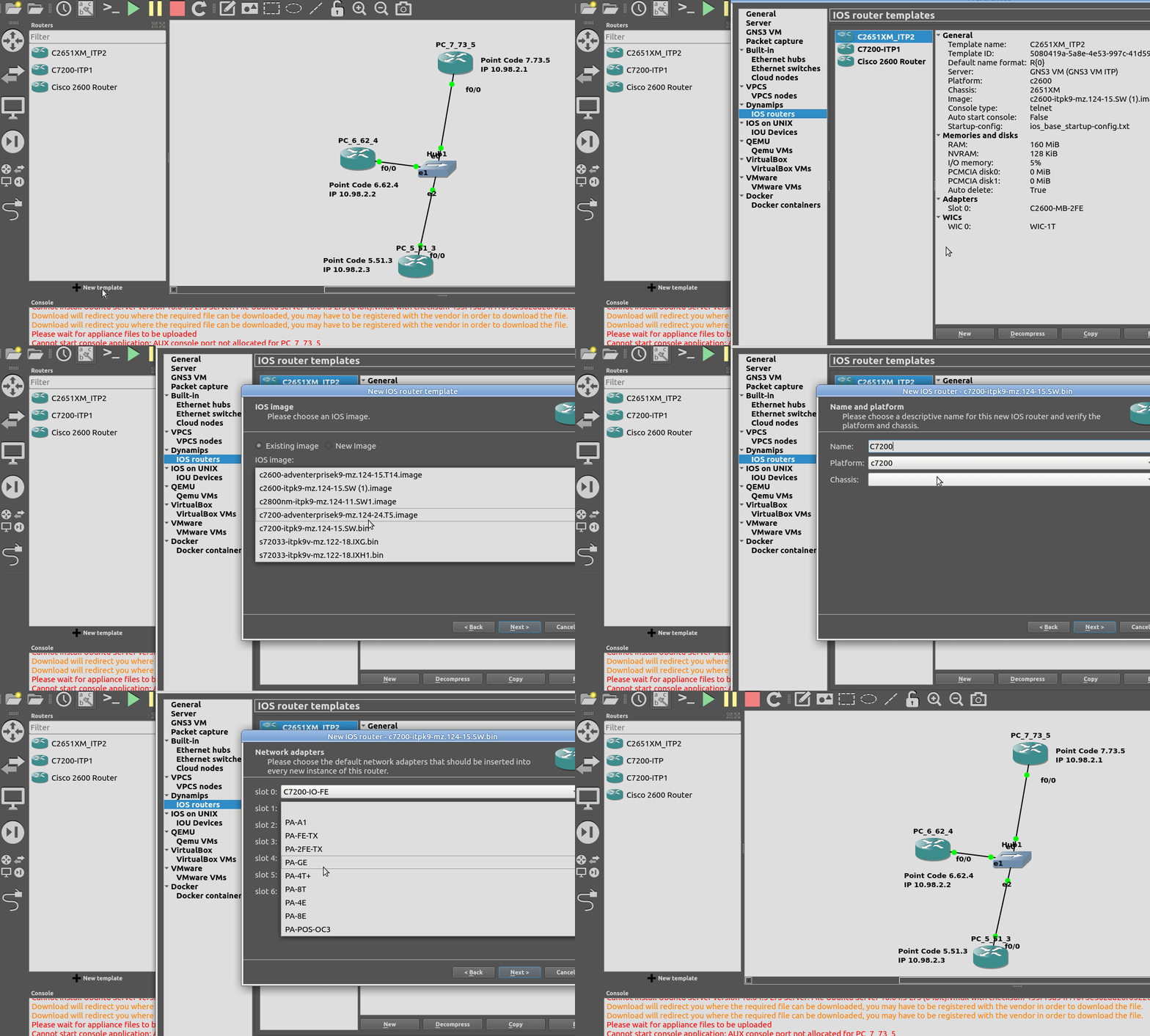
You will need a copy of the software image to load in. If you’ve got software entitlements you should be able to download it, the filename of the image I’m using for the 7200 series is c7200-itpk9-mz.124-15.SW.bin and if you go searching, you should find it.

Now we can start building networks with our Cisco STPs!

What we’re going to achieve

In this lab we’re going to introduce the basics of setting up STPs using Sigtran (SS7 over IP).

If you follow along, by the end of this post you should have two STPs talking Sigtran based SS7 to each other, and be able to see the SS7 packets in Wireshark.

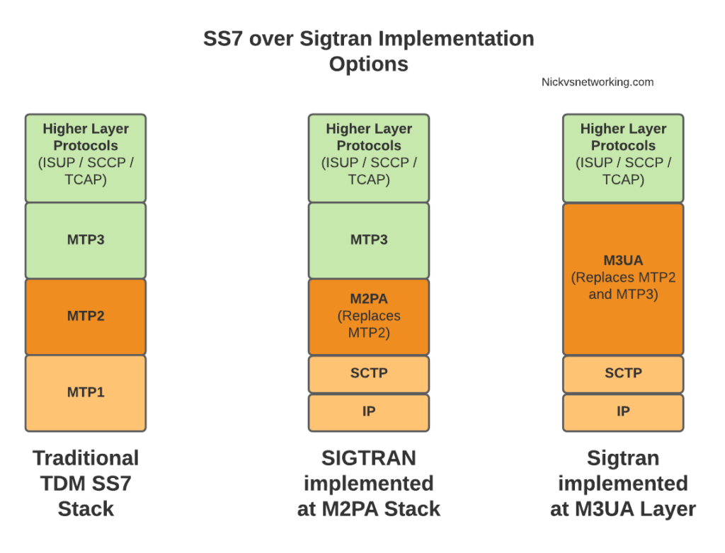
As we touched on in the last post, there’s a lot of different flavours and ways to implement SS7 over IP. For this post, we’re going to use M2PA (MTP2 Peer Adaptation Layer) to carry the MTP2 signaling, while MTP3 and higher will look the same as if it were on a TDM link. In a future post we’ll better detail the options here, the strengths and weaknesses of each method of transporting SS7 over IP, but that’s future us’ problem.

IP Connectivity

As we don’t have any TDM links, we’re going to do everything on IP, this means we have to setup the IP layer, before we can add any SS7/Sigtran stuff on top, so we’re going to need to get basic IP connectivity going between our Cisco STPs.

So for this we’ll need to set an IP Address on an interface, unshut it, link the two STPs. Once we’ve confirmed that we’ve got IP connectivity running between the two, we can get started on the Sigtran / SS7 side of things.

Let’s face it, if you’re reading this, I’m going to bet that you are probably aware of how to configure a router interface.

I’ve put a simple template down in the background to make a little more sense, which I’ve attached here if you want to follow along with the same addressing, etc.
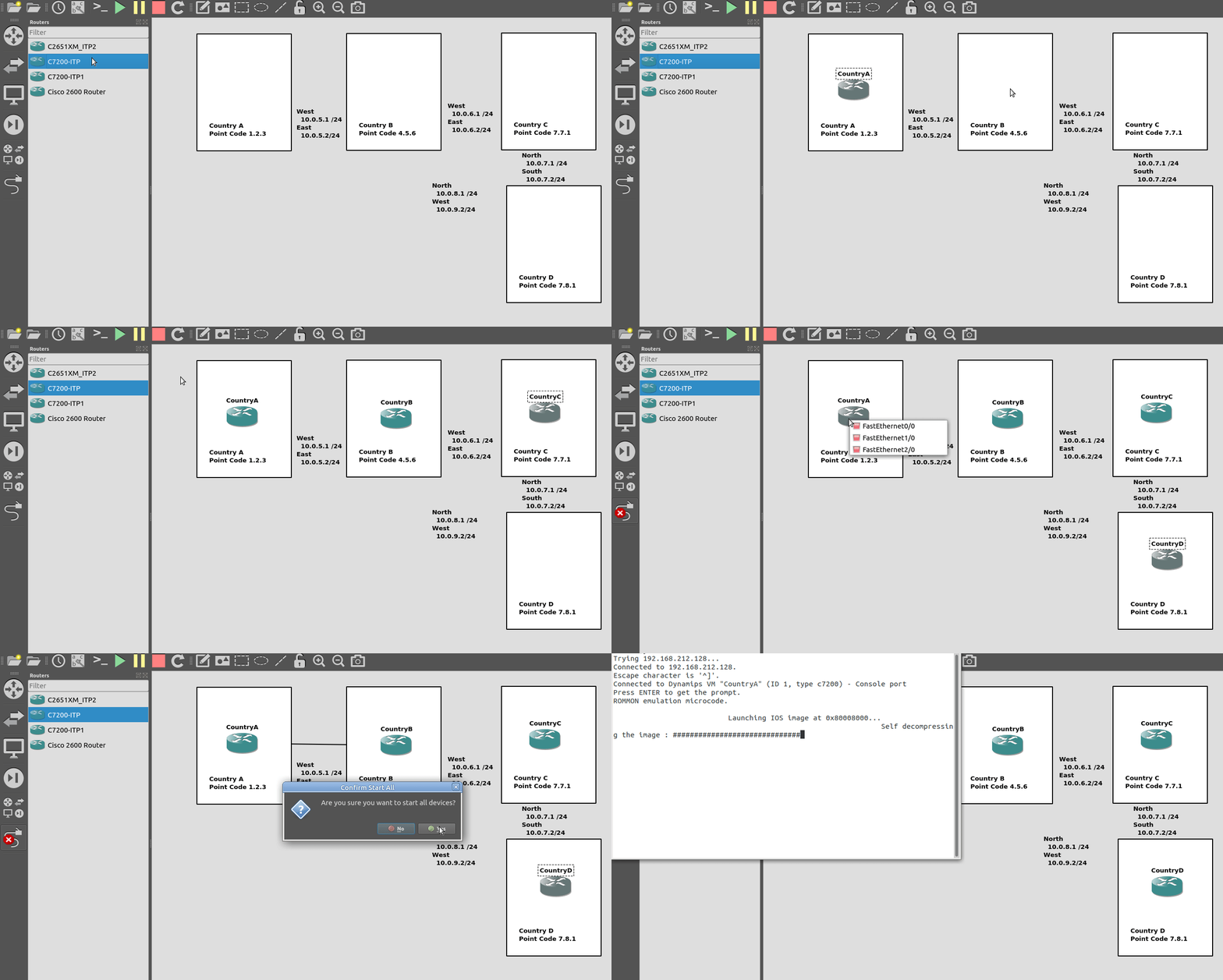
So we’ll configure all the routers in each country with an IP – we don’t need to configure IP routing. This means adjacent countries with a direct connection between them should be able to ping each other, but separated countries shouldn’t be able to.

So now we’ve got IP connectivity between two countries, let’s get Sigtran / SS7 setup!
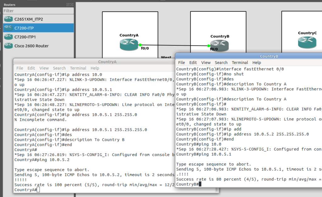
First we’ll need to define the basics, from configure-terminal in each of the Cisco STPs. We’ll need to set the SS7 variant (We’ll use ITU variant as we’re simulating international links), the network-indicator (This is an International network, so we’ll use that) and the point code for this STP (From the background image).

CountryA(config)#cs7 variant itu 
CountryA(config)#cs7 network-indicator international 
CountryA(config)#cs7 point-code 1.2.3

Repeat this step on Country A and Country B.

Next we’ll define a local peer on the STP. This is an instance of the Sigtran stack along with the port we’ll be listening on. Our remote peer will need to know this value to bring up the connection, the number specified is the port, and the IP is the IP it will bind on.

CountryA(config)#cs7 local-peer 1024
CountryA(config-cs7-lp)#local-ip 10.0.5.1

If we had multiple layer 3 IP Interfaces connecting Country A & Country B, we could list all the IP Addresses here for SCTP Multihoming.

Lastly on Country A we’ll need to define our Linkset to connect to our peer.

CountryA(config)#cs7 linkset ToCountryB 4.5.6
CountryA(config-cs7-ls)#link 0 sctp 10.0.5.2 1024 1024

Where the first 1024 is the local-peer port we configured earlier, and the second 1024 is the remote peer port we’re about to configure on Country B.

If we stop at this point and sniff the traffic from Country A to Country B, we’ll see SCTP INITs from Country A to Country B, as it tries to bring up the SCTP connection for our SS7 traffic, and the SCTP connection gets rejected by Country B.

This is of course, because we’ve only configured Country A at this stage, so let’s fix this by configuring Country B.

On CountryB, again we’ll set the basic parameters, our local-peer settings and the Linkset to bring up,

CountryB(config)#cs7 variant itu 
CountryB(config)#cs7 network-indicator international 
CountryB(config)#cs7 point-code 4.5.6
CountryB(config)#cs7 local-peer 1024
CountryB(config-cs7-lp)#local-ip 10.0.5.2
CountryB(config-cs7-lp)#exit
CountryB(config)#cs7 linkset ToCountryA 1.2.3
CountryB(config-cs7-ls)#link 0 sctp 10.0.5.1 1024 1024

If you’re still sniffing the traffic between Country A and Country B, you should see our SS7 connection come up.
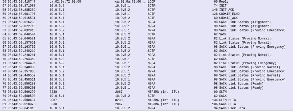
Wireshark trace of the connection coming up

The conneciton will come up layer-by-layer, firstly you’ll see the transport layer (SCTP) bring up an SCTP association, then MTP2 Peer Adaptation Layer (M2PA) will negotiate up to confirm both ends are working, then finally you’ll see MTP3 messaging.

If we open up an MTP3 packet you can see our Originating and Destination Point Codes.

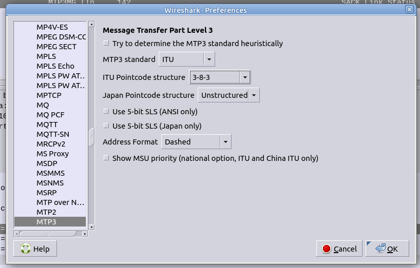
Notice in Wireshark the Point Codes don’t show up as 1-2-3, but rather 2067? That’s because they’re formatted as Decimal rather than 14 bit, this handy converter will translate them for you, or you can just change your preference in Wireshark’s decoders to use the matching ITU POint Code Structure.
From the CLI on one of the two country STPs we can run some basic commands to view the status of all SS7 components and Linksets.

And there you have it! Basic SS7 connectivity!

There is so much more to learn, and so much more to do!
By bringing up the link we’ve barely scratched the surface here.

Some homework before the next post, link all the other countries shown together, with Country D having a link to Country C and Country B. That’s where we’ll start in the lab – Tip: You’ll find you’ll need to configure a new cs7 local-peer for each interface, as each has its own IP.
Demystifying SS7 & Sigtran (With Labs!) – Part 2 – Ingredients Needed

This is part of a series of posts looking into SS7 and Sigtran networks. We cover some basic theory and then get into the weeds with GNS3 based labs where we will build real SS7/Sigtran based networks and use them to carry traffic.

So one more step before we actually start bringing up SS7 / Sigtran networks, and that’s to get a bit of a closer look at what components make up SS7 networks.

Recap: What is SS7?

SS7 is the name given to the protocol stack used almost exclusively in the telecommunications space. SS7 isn’t just one protocol, instead it is a suite of protocols.
In the same way when someone talks about IP networking, they’re typically not just talking about the IP layer, but the whole stack from transport to application, when we talk about an SS7 network, we’re talking about the whole stack used to carry messages over SS7.

And what is SIGTRAN?

Sigtran is “Signaling Transport”. Historically SS7 was carried over TDM links (Like E1 lines).

As the internet took hold, the “Signaling Transport” working group was formed to put together the standards for carrying SS7 over IP, and the name stuck.

I’ve always thought if I were to become a Mexican Wrestler (which is quite unlikely), my stage name would be DSLAM, but SIGTRAN comes a close second.

Today when people talk about SIGTRAN, they mean “SS7 over IP”.

What is in an SS7 Network?

SS7 Networks only have 3 types of network elements:

  • Service Switching Points (SSP)
  • Service Transfer Points (STP)
  • Service Control Points (SCP)

Service Switching Points (SSP)

Service Switching Points (SSPs) are endpoints in the network.
They’re the users of the connectivity, they use it to create and send meaningful messages over the SS7 network, and receive and process messages over the SS7 network.

Like a PC or server are IP endpoints on an IP Network, which send and receive messages over the network, an SSP uses the SS7 network to send and receive messages.

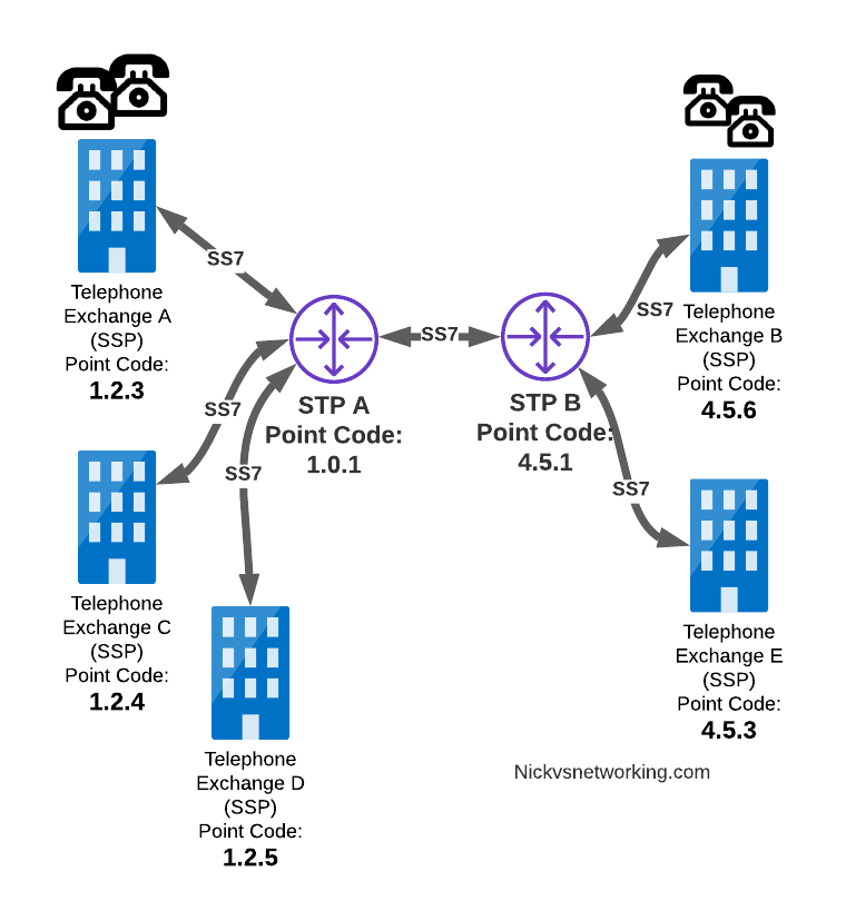
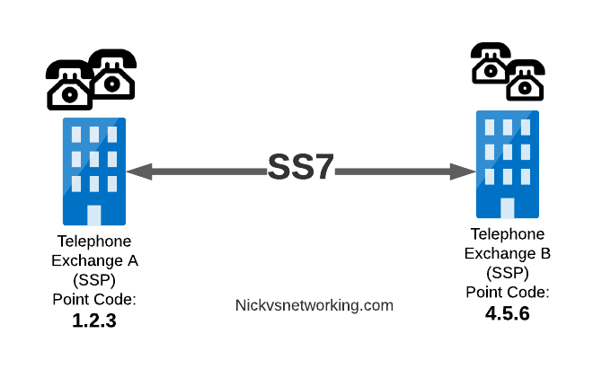
In a PSTN context, your local telephone exchange is most likely an SS7 Service Switching Point (SSP) as it creates traffic on the SS7 network and receives traffic from it.

A call from a user on one exchange to a user on another exchange could go from the SSP in Exchange A, to the SSP in Exchange B, in the same way you could send data between two computers by connecting directly between them with an Ethernet crossover cable.

Messages between our two exchanges are addressed using Point Codes, which can be thought of a lot like IP Addresses, except shorter.

In the MTP3 header of each SS7 message is the Destination Point Code, and the Origin Point Code.

When Telephone Exchange A wants to send a message over SS7 to Telephone Exchange B, the MTP header would look like:

MTP3 Header:
Origin Point Code:      1.2.3
Destination Point Code: 4.5.6

Service Transfer Points (STP)

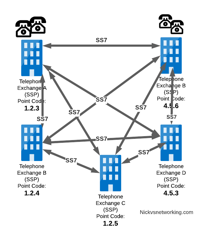
Linking each SSP to each other SSP has a pretty obvious problem as our network grows.

What happens if we’ve got hundreds of SSPs? If we want a full-mesh topology connecting every SSP to every other SSP directly, we’d have a rats nest of links!

A “full-mesh” approach for connecting SSPs does not work at scale, so STPs are introduced

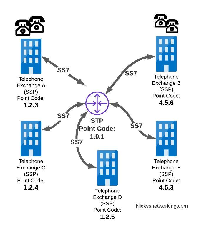
So to keep things clean and scalable, we’ve got Signalling Transfer Points (STPs).

STPs can be thought of like Routers but in an SS7 network.

When our SSP generates an SS7 message, it’s typically handed to an STP which looks at the Destination Point Code, it’s own routing table and routes it off to where it needs to go.

STP acting as a central router to connect lots of SSPs

This means every SSP doesn’t require a connection to every other SSP. Instead by using STPs we can cut down on the complexity of our network.

When Telephone Exchange A wants to send a message over SS7 to Telephone Exchange B, the MTP header would look the same, but the routing table on Telephone Exchange A would be setup to send the requests out the link towards the STP.

MTP3 Header:
Origin Point Code:      1.2.3
Destination Point Code: 4.5.6

Linksets

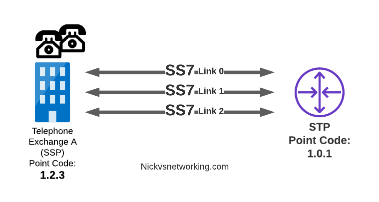
Between SS7 Nodes we have Linksets. Think of Linksets as like LACP or Etherchannel, but for SS7.

You want to have multiple links on every connection, for sharing out the load or for redundancy, and a Linkset is a group of connections from one SS7 node to another, that are logically treated as one link.

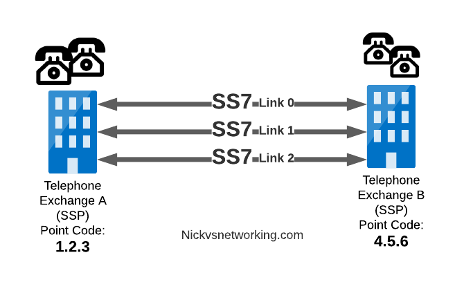
Link between an SSP and STP with 3 linksets

Each of the links in a Linkset is identified by a number, and specified in in the MTP3 header’s “Signaling Link Selector” field, so we know what link each message used.

MTP3 Header:
Origin Point Code:       1.2.3
Destination Point Code:  4.5.6
Signaling Link Selector: 2

Service Control Point (SCP)

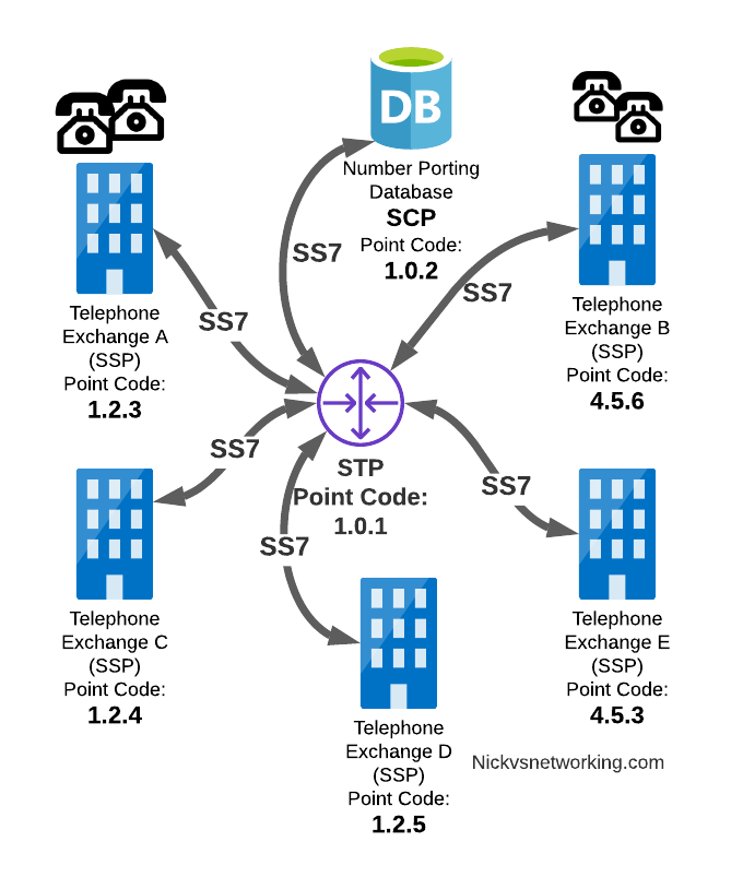
Somewhere between a Rolodex an relational database, is the Service Control Point (SCP).

For an exchange (SSP) to route a call to another exchange, it has to know the point code of the destination Exchange to send the call to.
When fixed line networks were first deployed this was fairly straight forward, each exchange had a list of telephone number prefixes and the point code that served each prefix, simple.

But then services like number porting came along when a number could be moved anywhere.
Then 1800/0800 numbers where a number had to be translated back to a standard phone number entered the picture.

To deal with this we need a database, somewhere an SSP can go to query some information in a database and get a response back.

This is where we use the Service Control Point (SCP).

Keep in mind that SS7 long predates APIs to easily lookup data from a service, so there was no RESTful option available in the 1980s.

When a caller on a local exchange calls a toll free (1800 or 0800 number depending on where you are) number, the exchange is setup with the Point Code of an SCP to query with the toll free number, and the SCP responds back with the local number to route the call to.

While SCPs are fading away in favor of technology like DNS/ENUM for Local Number Portability or Routing Databases, but they are still widely used in some networks.

Getting to know the Signalling Transfer Point (STP)

As we saw earlier, instead of a one-to-one connection between each SS7 device to every other SS7 device, Signaling Transfer Points (STP) are used, which act like routers for our SS7 traffic.

The STP has an internal routing table made up of the Point Codes it has connections to and some logic to know how to get to each of them.

Like a router, STPs don’t really create SS7 traffic, or consume traffic, they just receive SS7 messages and route them on towards their destination.

Ok, they do create some traffic for checking links are up, etc, but like a router, their main job is getting traffic where it needs to go.

When an STP receives an SS7 message, the STP looks at the MTP3 header. Specifically the Destination Point Code, and finds if it has a path to that Point Code. If it has a route, it forwards the SS7 message on to the next hop.

Like a router, an STP doesn’t really concern itself with anything higher than the MTP3 layer – As point codes are set in the MTP3 layer that’s the only layer the STP looks at and the upper layers aren’t really “any of its business”.

STPs don’t require a direct connection (Linkset) from the Originating Point Code straight to the Destination Point Code. Just like every IP router doesn’t need a direct connection to ever other network.
By setting up a routing table of Point Codes and Linksets as the “next-hop”, we can reach Destination Point Codes we don’t have a direct Linkset to by routing between STPs to reach the final Destination Point Code.

Let’s work through an example:

And let’s look at the routing table setup on STP-A:

STP A Routing Table:
1.2.3 - Directly attached (Telephone Exchange A)
1.2.4 - Directly attached (Telephone Exchange C)
1.2.5 - Directly attached (Telephone Exchange D)
4.5.1 - Directly attached (STP-B)
4.5.3 - Via STP-B
4.5.6 - Via STP-B

So what happens when Telephone Exchange A (Point Code 1.2.3) wants to send a message to Telephone Exchange E (Point Code 4.5.3)?
Firstly Telephone Exchange A puts it’s message on an MTP3 payload, and the MTP3 header will look something like this:

MTP3 Header:
Origin Point Code:       1.2.3
Destination Point Code:  4.5.3
Signaling Link Selector: 1

Telephone Exchange A sends the SS7 message to STP A, which looks at the MTP3 header’s Destination Point Code (4.5.3), and then in it’s routing table for a route to the destination point. We can see from our example routing table that STP A has a route to Destination Point Code 4.5.3 via STP-B, so sends it onto STP-B.

For STP-B it has a direct connection (linkset) to Telephone Exchange E (Point Code 4.5.3), so sends it straight on

Like IP, Point Codes have their own form of Variable-Length-Subnet-Routing which means each STP doesn’t need full routing info for every Destination Point Code, but instead can have routes based on part of the point code and a subnet mask.

But unlike IP, there is no BGP or OSPF on SS7 networks. Instead, all routes have to be manually specified.

For STP A to know it can get messages to destinations starting with 4.5.x via STP B, it needs to have this information manually added to it’s route table, and the same for the return routing.

Sigtran & SS7 Over IP

As the world moved towards IP enabled everything, TDM based Sigtran Networks became increasingly expensive to maintain and operate, so a IETF taskforce called SIGTRAN (Signaling Transport) was created to look at ways to move SS7 traffic to IP.

When moving SS7 onto IP, the first layer of SS7 (MTP1) was dropped, as it primarily concerned the physical side of the network. MTP2 didn’t really fit onto an IP model, so a two options were introduced for transport of the MTP2 data, M2PA (Message Transfer Part 2 User Peer-to-Peer Adaptation Layer) and M2UA (MTP2 User Adaptation Layer) were introduced, which rides on top of SCTP.
This means if you wanted an MTP2 layer over IP, you could use M2UA or M2TP.

SCTP is neither TCP or UDP. I’ve touched upon SCTP on this blog before, it’s as if you took the best bits of TCP without the issues like head of line blocking and added multi-homing of connections.

So if you thought all the layers above MTP2 are just transferred, unchanged on top of our M2PA layer, that’s one way of doing it, however it’s not the only way of doing it.

There are quite a few ways to map SS7 onto IP Networks, which we’ll start to look into it more detail, but to keep it simple, for the next few posts we’ll be assuming that everything above MTP2/M2PA remain unchanged.

In the next post, we’ll get some actual SS7 traffic flowing!

Demystifying SS7 & Sigtran Networks (With Labs!) – Part 1 – Intro

This is part of a series of posts looking into SS7 and Sigtran networks. We cover some basic theory and then get into the weeds with GNS3 based labs where we will build real SS7/Sigtran based networks and use them to carry traffic.

If you use a mobile phone, a VoIP system or a copper POTS line, there’s a high chance that somewhere in the background, SS7 based signaling is being used.

The signaling for GSM, UMTS and WCDMA mobile networks all rely on SS7 based signaling, and even today the backbone of most PSTN traffic relies SS7 networks. To many this is mysterious carrier tech, and as such doesn’t get much attention, but throughout this series of posts we’ll take a hands-on approach to putting together an SS7 network using GNS3 based labs and connect devices through SS7 and make some stuff happen.

Overview of SS7

Signaling System No. 7 (SS7/C7) is the name for a family of protocols originally designed for signaling between telephone switches. In plain English, this means it was used to setup and teardown large volumes of calls, between exchanges or carriers.

When carrier A and Carrier B want to send calls between each other, there’s a good chance they’re doing it over an SS7 Network.

But wait! SIP exists and is very popular, why doesn’t everyone just use SIP?
Good question, imaginary asker. The answer is that when SS7 came along, SIP was still almost 25 years away from being defined.
Yes. It’s pretty old.

SS7 isn’t one protocol, but a family of protocols that all work together – A “protocol stack”.
The SS7 specs define the lower layers and a choice of upper layer / application protocols that can be carried by them.

The layered architecture means that the application layer at the top can be changed, while the underlying layers are essentially the same.

This means while SS7’s original use was for setting up and tearing down phone calls, this is only one application for SS7 based networks. Today SS7 is used heavily in 2G/3G mobile networks for connectivity between core network elements in the circuit-switched domain, for international roaming between carriers and services like Local Number Portability and Toll Free numbers.

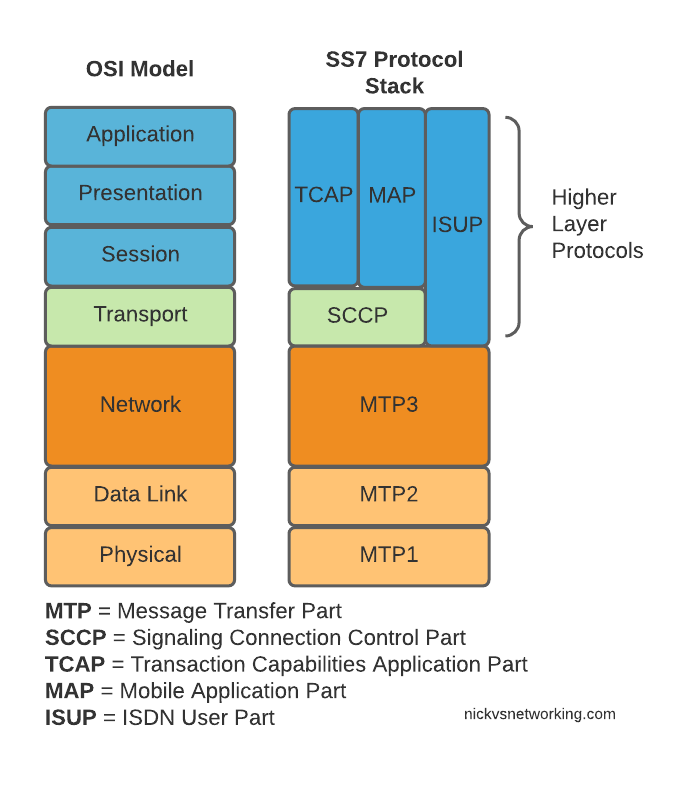
Here’s the layers of SS7 loosely mapped onto the OSI model (SS7 predates the OSI model as well):

OSI Model (Left) and SS7 Protocol Stack (Right)

We do have a few layers to play with here, and we’ll get into them all in depth as we go along, but a brief introduction to the underlying layers:

MTP 1 – Message Transfer Part 1

This is our physical layer. In this past this was commonly E1/T1 lines.

It’s responsible for getting our 1s and 0s from one place to another.

MTP 2 – Message Transfer Part 2

MTP2 is responsible for the data link layer, handling reliable transfer of data, in sequence.

MTP 3 – Message Transfer Part 3

The MTP3 header contains an Originating and a Destination Point Code.

These point codes can be thought of as like an IP Address; they’re used to address the source and destination of a message. A “Point Code” is the unique address of a SS7 Network element.

MTP3 header showing the Destination Point Code (DPC) and Origin Point Code (OPC) on a National Network, carrying ISUP traffic

Every message sent over an SS7 network will contain an Origin Point Code that identifies the sender, and a Destination Point Code that identifies the intended recipient.

This is where we’ll bash around at the start of this course, setting up Linksets to allow different devices talking to each other and addressing each other via Point Codes.

The MTP3 header also has a Service Indicator flag that indicates what the upper layer protocol it is carrying is, like the Protocol indicator in IPv4/IPv6 headers.

A Signaling Link Selector indicates which link it was transported over (did I mention we can join multiple links together?), and a Network Indicator for determining if this is signaling is at the National or International level.

TUP/MAP/SCCP/ISUP

These are the “higher-layer” protocols. Like FTP sits on top of TCP/IP, a SS7 network can transport these protocols from their source to their destination, as identified by the Origin Point Code (OPC), to the Destination Point Code (DPC), as specified in the MTP3 header.

We’ll touch on these protocols more as we go on. SCCP has it’s own addressing on top of the OPC/DPC (Like IP has IP Addressing, but TCP has port numbers on top to further differentiate).

Why learn SS7 today?

SS7 and SIGTRAN are still widely in use in the telco world, some of it directly, other parts derived / evolved from it.

So stick around, things are about to get interesting!

Huawei BBU 3900 Architecture

Huawei Baseband Cheat Sheet

Baseband Units (UBBP)

CardMax LTE Cells
UBBPd33×20 MHz 2T2R
UBBPd43×20 MHz 4T4R
UBBPd56×20 MHz 2T2R OR 3×20 MHz 4T4R
UBBPd66×20 MHz 4T4R
UBBPe13×20 MHz 2T2R
UBBPe23×20 MHz 4T4R
UBBPe36×20 MHz 2T2R OR 3×20 MHz 4T4R
UBBPe46×20 MHz 4T4R OR 3×20 MHz 8T8R
Max Cells in LTE FDD

Main Processing and Transmission (LMPT/UMPT)

In some instances two boards can be used together to double the max cells or max throughput values.

CardMax CellsMax Throughput
(at MAC Layer)
Max UEs
(In RRC Connected)
LMPT18 Cells (4T4R)Uplink 300Mbps
Downlink 450Mbps
5400
UMPTa36 Cells (4T4R)Aggregate 1.5Gbps10800
UMPTb136 Cells (4T4R)Aggregate 1.5Gbps10800
UMPTb236 Cells (4T4R)Aggregate 1.5Gbps10800
UMPTb336 Cells (4T4R)Aggregate 2Gbps10800
UMPTb936 Cells (4T4R)Aggregate 2Gbps10800
UMPTe72 Cells (4T4R)Aggregate 10Gbps14400

Lifecycle of a Dedicated Bearer – From Flow-Description AVP to Traffic Flow Templates

To support Dedicated Bearers we first have to have a way of profiling the traffic, to classify the traffic as being the type we want to provide the Dedicated Bearer for.

The first step involves a request from an Application Function (AF) to the PCRF via the Rx interface.

The most common type of AF would be a P-CSCF. When a VoLTE call gets setup the P-CSCF requests that a dedicated bearer be setup for the IP Address and Ports involved in the VoLTE call, to ensure users get the best possible call quality.

But Application Functions aren’t limited to just VoLTE – You could also embed an Application Function into the server for an online game to enable a dedicated bearer for users playing that game, or a sports streaming app that detects when a user starts streaming sports and creates a dedicated bearer for that user to send the traffic down.

The request to setup a dedicated bearer comes in the form of a Diameter request message from the AF, using the Rx reference point, typically from the P-CSCF to the PCRF in the network in an “AA-Request”.

Of main interest in the AA-Request is the Media Component AVP, that contains all the details needed to identify the traffic flow.

Now our PCRF is in charge of policy, and know which P-GW is serving the required subscriber. So the PCRF takes this information and sends a Gx Re-Auth Request to the PCEF in the P-GW serving the subscriber, with a Charging Rule the PCEF in the P-GW needs to install, to profile and apply QoS to the bearer.

So within the Gx Re-Auth Request is the Charging-Rule Definition, made up of Flow-Description AVP which I’ve written about here, that is used to identify and profile traffic flows and QoS parameters to apply to matching traffic.

Charging Rule Definition’s Flow-Information AVPs showing the information needed to profile the traffic

The QoS Description AVP defines which QoS parameters (QCI / ARP / Guaranteed & Maximum Bandwidth) should be applied to the traffic that matches the rules we just defined.

QoS information AVP
QoS Information AVP showing requested QoS Parameters

The P-GW sends back a Gx Re-Auth Answer, and gets to work actually setting up these bearers.

With the rule installed on the PCEF, it’s time to get this new bearer set up on the UE / eNodeB.

The P-GW sends a GTPv2 “Create Bearer Request” to the S-GW which forwards it onto the MME, to setup / define the Dedicated Bearer to be setup on the eNodeB.

GTPv2 “Create Bearer Request” sent by the P-Gw to the S-GW forwarded from the S-GW to the MME

The MME translates this into an S1 “E-RAB Setup Request” which it sends to the eNodeB to setup,

S1 E-RAB Setup request showing the E-RAB to be setup

Assuming the eNodeB has the resources to setup this bearer, it provides the details to the UE and sets up the bearer, sending confirmation back to the MME in the S1 “E-RAB Setup Response” message, which the MME translates back into GTPv2 for a “Create Bearer Response”

All this effort to keep your VoLTE calls sounding great!