Meta: The Australian government made up it’s mind some time ago that Huawei would be blacklisted from providing equipment for 5G networks.
Several other countries have adopted the same policy in regards, and as such, deployed Huawei tech is being replaced, and some of it filters down to online auction sites…
So I kind of purchased an item described as “Huawei BBU3900” with a handful of unknown cards and 2 LRFU units, for just over $100.
My current lab setup is a single commercial picocell and a draw of SDR hardware that works with mixed results, so the idea of having a commercial macro cell to play with seemed like a great idea, I put lowball offer in and the seller accepted.
Now would be a good time to point out I don’t know much about RAN and it’s been a long time since I’ve been working on power systems, so this is shaping up to be a fun project.
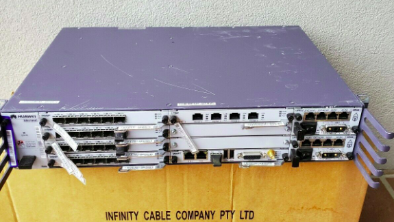
Photo from the listing 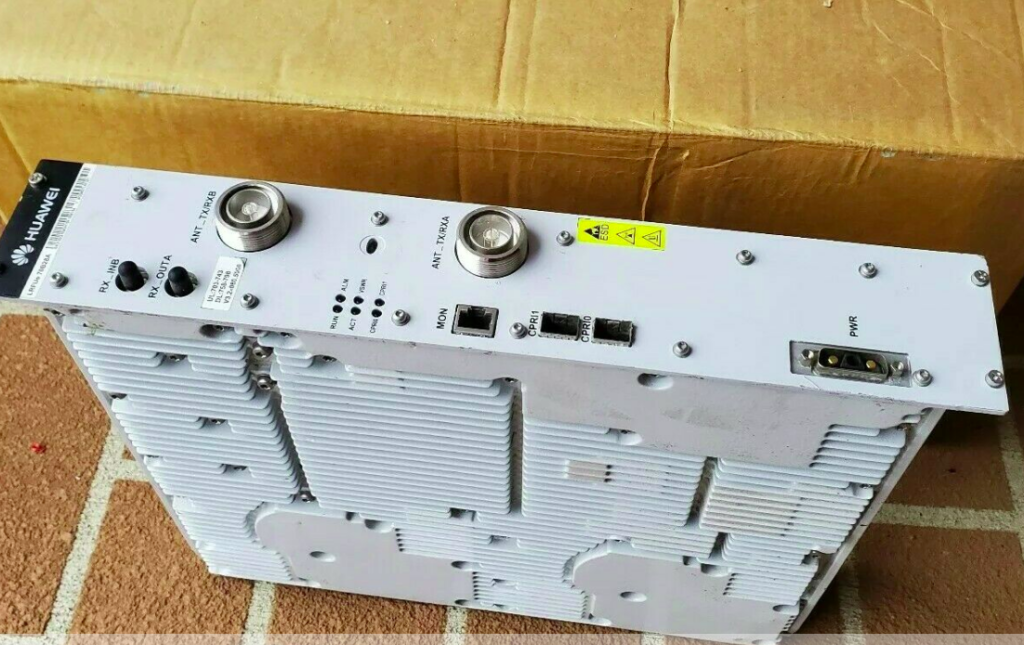
Photo from the listing
I did a Huawei RAN course years ago and remembered the rough ingredients required for LTE:
- You needed either RRUs (Remote Radio Units) or RFUs (Radio Frequency Units) to handle the RF side of things.
RRUs are designed for outdoor use (such as mounting on the tower) and RFUs are designed for indoor use, like mounting in a cabinet.
I’ve ended up with two LRFUe units, which I can join together for 2x MIMO, operate on Band 28 and can put out a whopping 80W of transmit power, yes I’m going to need some big attenuators… - You need a Baseband Processor card to tell the Radio units what do do.
The card connects the CPRIs (Typically optic fiber links) between the radio units and the baseband.
The chassis I purchased came with a stack of WBBP (For WCDMA) cards and a single LBBP card for LTE. The LBBP card has 6 SFP ports for the CPRI interfaces, which is more than enough for my little lab. (You can also daisy-chain CPRIs so I’m not even limited to 6 Radio Units.) - You need a backplane and a place for the cards to live – this is the BBU3900 chassis. It’s got basic switching to allow communication between cards, a chassis to distribute power and cooling.
(Unlike the Ericson units there is actually a backplane for communications in the Huawei chassis – the Ericsson RBS series has is just power and cooling in the chassis) - Optional – Dedicated transmission card, I’ve ended up with a Universal Transmission Processor (UTRP9) with 2x Gig Ethernet and 2x Fast Ethernet ports for transmission. This will only work for GSM and UMTS though, not LTE, so not much use for me.
- You need something to handle main processing (LTE / Universal Main Processing and Transmission Unit (LMPT / UMPT)).
Unfortunately the unit I’ve ended up with only came with a WMPT (For WCDMA), so back online to find either an LMPT (LTE) or UMPT (Universal (2G/3G/4G))… - You need a Universal Power and Environment Module (UPEU) to power up the chassis and handle external IO for things like temperature alarms, door sensors and fire detectors. This chassis has two for redundancy / extra IO & extra power capacity.
So in order to get this running I still need quite a few components:
- Attenuators – I’ll be able to turn the power down, sure, but not to the levels required to be legal.
- Antennas – These are FDD units, so I’ll need two antennas for each RFU, on Band 28
- Feeder Cables – To connect the antennas
- SMF cables and SFPs – I’ve got a pile in my toolbox, but I’ll need to work out what’s supported by these units
- A big -48vDC rectifier (I got the BBU3900 unit powered up with an existing supply I had, but I’m going to need something bigger for the power hungry RFUs)
- DC Distribution Unit – Something to split the DC between the RFUs and the BBU, and protect against overload / short
- USB-Network adapter – For OAM access to the unit – Found these cheaply online and got one on the way
- The LTE Main Processing & Transmission (LMPT) card – Ordered a second hand one from another seller
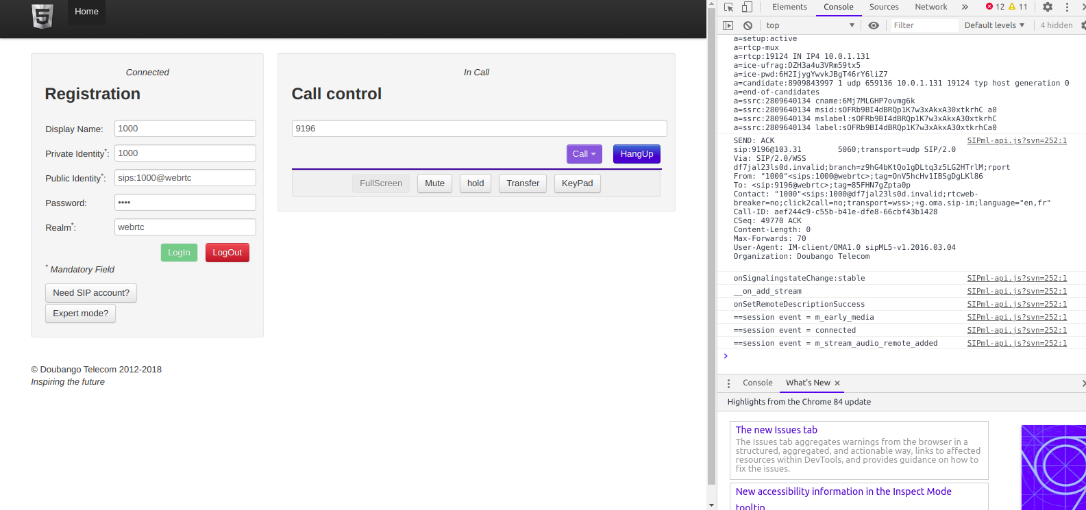
I powered up the BTA3900 and sniffed the traffic, and can see it trying to reach an RNC.
Unfortunately with no open source RNC options I won’t be posting much on the topic of UMTS or getting the UMTS/WCDMA side of things on the air anytime soon…
So that’s the start of the adventure.
I don’t know if I’ll get this all working, but I’m learning a lot in the process, and that’s all that really matters…
Note: I think this is the course I did from Huawei on the BBU3900…