SIP was designed to be flexible in it’s operation, and for, where possible, messages to take the most direct path.
For example I can use a Registrar function of a proxy to find the IP of a registered endpoint, but once a dialog is setup, why should the proxy be involved? The endpoint & I can take it from here, and can talk directly to each other using the address in the Contact header.
This works really well in some scenarios, as I described above you can have the registrar proxy setup the introduction and then off you go.
Other scenarios this doesn’t work quite so well, for example if the call needs to be billed. To charge correctly, the proxy needs to know when the call ends to know when to stop charging.
If the endpoint we’re talking to is behind a NAT, the NAT might just be locked to the IP of the registrar proxy and drop your traffic.
The Record-Route header exists to address this.
If a proxy adds a Record-Route header, it means it’ll sit in the middle of any future requests in this dialog, and route them back through the proxy.
By adding a Record-Route header on the proxy for our billing example, our proxy will forward inline all the messages between the two end points for that dialog, including the BYE so the proxy knows when to stop charging.
For the NAT scenario we described the Proxy will add a Record-Route header and forward all the messages between the two endpoints, so NAT won’t be an issue as the source IP of the packets will be the same as the proxy.
There was a bit of confusion in regards to implementation so to address this IETF wrote RFC 5658 to address Record-Route Issues in SIP.
Content-Type application/sdp is something you’ll see a whole lot when using SIP for Voice over IP, especially in INVITEs and 200 OK responses.
This is because SIP uses SDP to negotiate the media setup.
While Voice over IP uses RTP for media, and SIP for signalling, the meat in this sandwich is SDP, used to negotiate the RTP parameters and payloads before going ahead.
Without SDP you’d just have random unidentified RTP streams going everywhere and no easy way to correlate them back to a Session (SIP) or guarantee both endpoints support the same codec (RTP payload).
Enter SDP, the Session Description Protocol, before any RTP is sent, SDP advertises capabilities (which codecs to use), contact information, port information (which port to send the RTP stream to) and attempts to negotiate a media session both endpoints can support.
SDP is designed to be lightweight, while SIP uses human readable headers like To and From, SDP does away with this in favour of single letters representing what that header contains.
As an interesting aside, SIP at one stage also offered one-letter headers to make it smaller on the wire, but this never really took off.
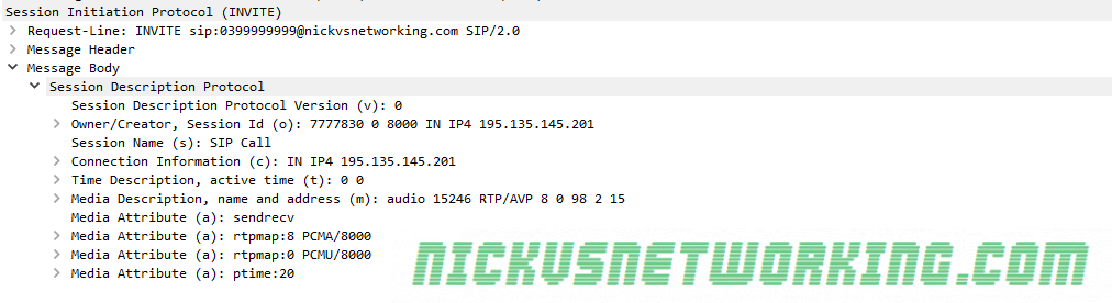
Here we can see what an SDP header looks like, showing the Session ID, Session Name, Connection Information and Media Descriptions.
SDP from an INVITE
Let’s dig a little deeper and have a look at what this SDP header actually shows that’s useful to us.
The SDP Offer
Session Identifiers
Session information
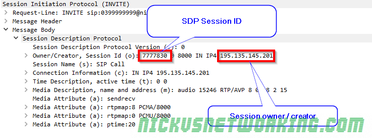
The Owner / Creator & Session ID header (abbreviated to o=) contains the SDP session ID and the session owner / creator information. This contains the SDP Session ID and the IP Address / FQDN of the owner or creator of this session. In this case the SDP Session ID is 777830 and the Session owner / creator is 195.135.145.201.
Connection Information
Receiving / listening information
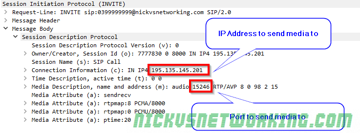
Next up we’ve got the connection information header (abbreviated to c=) which contains the IP Address we want the incoming RTP stream sent to. In this example it’s coming IN on IPv4 address 192.135.154.201.
The Media Description header (m=) also contains the port we want to receive the audio on, 15246.
So in summary we’re telling the called party that we’ll be listening on IP Address 192.135.154.201 on port 15246, so they should send their RTP audio stream to that address & port.
Media Attributes
Media attributes
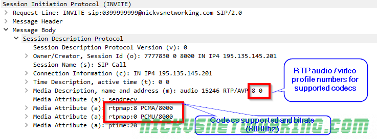
The Media Description header (abbreviated to m=) contains a name and address, in this case it’s audio, and sent to address (port) 15246.
After that we’ve got the RTP Audio / Video profile numbers. Because SDP is designed to be lightweight instead of saying PCMA, PCMU here each codec is assigned a number by IANA that translates to a codec. The full list is here, but 8 is equal to PCMA and 0 is equal to PCMU.
So from the Media Description header we can learn that it’s an Audio session, with media to be sent to port 15246, via RTP using PCMA or PCMU.
Different codecs can have different bitrates, so by using the Media Attribute header (Abbreviated to a=) we can set the bitrates for each. In this case both PCMA and PCMU are using a bitrate of 8000.
Summary
So to summarise we’ve told the party we’re calling our session ID is 777830 and it’s owned / created by 195.135.145.201. We support PCMA and PCMU at 8000Hz, and we’ll be listening on IPv4 on 195.135.145.201 on port 15246 for them to send their audio stream to.
The SDP Answer
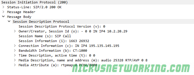
Next we’ll take a look at the SDP from a 200 OK response, and work out what our session will look like.
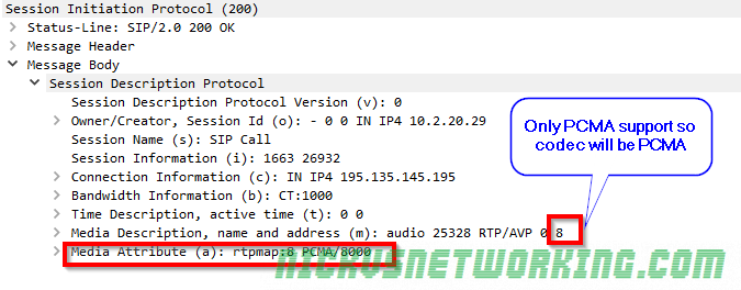
Codec Selection
We can see this device only supports PCMA, which makes codec selection pretty easy, it’s going to be PCMA as that was also supported in the SDP offer contained in the initial INVITE.
In the scenario where both devices support the same codecs, the order in which the codecs are listed defines what codec is selected.
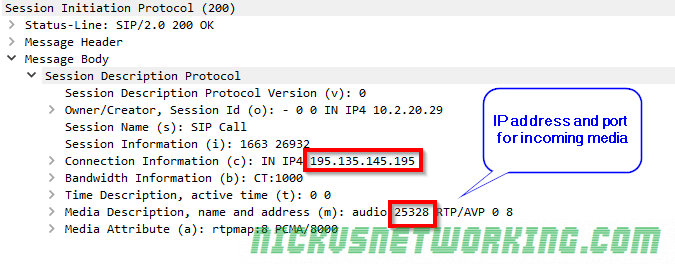
Connection Information
Like in the SDP offer we can see that we’re requesting incoming RTP / media to be sent to, in this case we’re asking for the RTP / media on 195.135.145.195 port 25328
Final Steps
Generally after the 200 OK is received an ACK is sent and media starts flowing in both directions between endpoints.
In this example 195.135.145.195 will send their audio (aka media / RTP) to 195.135.145.201 on port 15246 (called party to the caller) and 195.135.145.201 will send their audio to 195.135.145.195 on port 25328 (calling party to the called party).
It’s always worth keeping in mind that SIP doesn’t have to be used for Voice, nor does it have to use SDP, nor does SDP have to be used with SIP, it can be used with other protocols (IAX, H.323), and doesn’t have to negotiate RTP sessions, but could negotiate anything.
That said, the SIP – SDP – RTP sandwich is pretty ubiquitous for good reason, and while it’s true that none of these protocols require each other, the truth is, most of their usage is with one-another and it’s easier to just say “SIP uses SDP” and “SDP uses RTP” than continually saying “SIP can use SDP” and “SDP can use RTP” etc.
Branch IDs were introduced in RFC 3261, to help keep differentiate all the different transactions a device or proxy might be involved in.
The answer isn’t that exciting. IETF picked the 7 character long prefix as a magic cookie so older SIP servers (RFC 2543 compliant only) wouldn’t pick up the value due to it’s length.
The branch ID inserted by an element compliant with this specification MUST always begin with the characters “z9hG4bK”. These 7 characters are used as a magic cookie (7 is deemed sufficient to ensure that an older RFC 2543 implementation would not pick such a value), so that servers receiving the request can determine that the branch ID was constructed in the fashion described by this specification (that is, globally unique).
As to why z9hG4bK, instead of any other random 7 letter string, I haven’t been able to find an answer, but it’s as good as any random 7 letter string I guess.
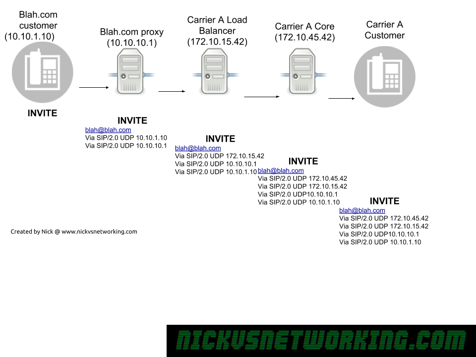
The SIP Via header is added by a proxy when it forwards a SIP message onto another destination,
When a response is sent the reverse is done, each SIP proxy removes their details from the Via header and forwards to the next Via header along.
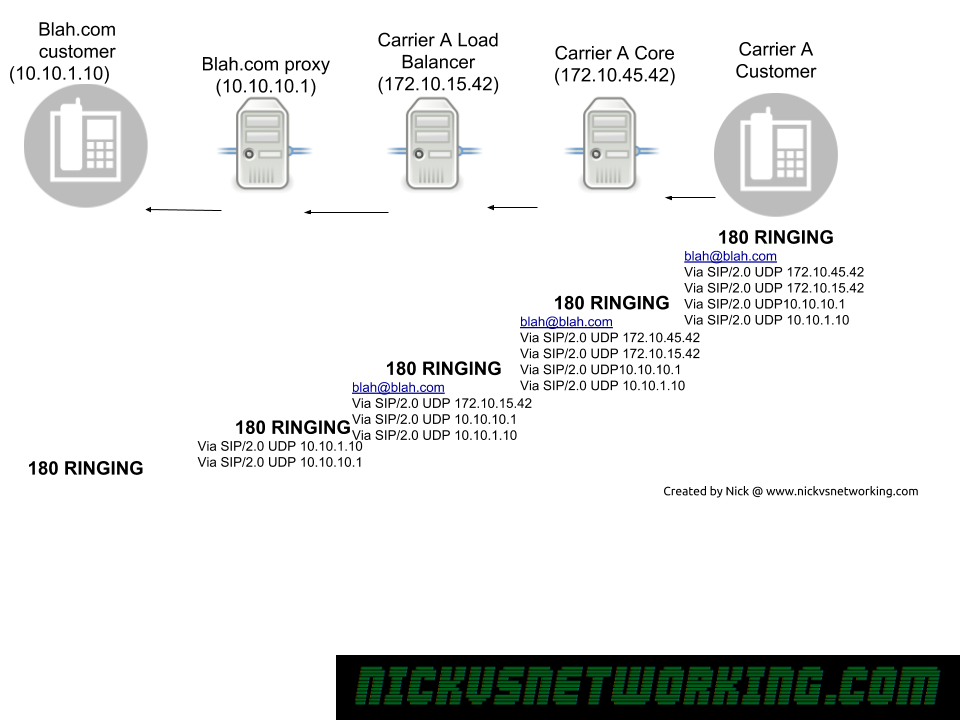
SIP Via headers in action
As we can see in the example above, each proxy adds it’s own address as a Via header, before it uses it’s internal logic to work out where to forward it to, and then forward on the INVITE.
Now because all our routing information is stored in Via headers when we need to route a Response back, each proxy doesn’t need to consult it’s internal logic to work out where to route to, but can instead just strip it’s own address out of the Via header, and then forward it to the next Via header IP Address down in the list.
Via headers are also used to detect looping, a proxy can check when it receives a SIP message if it’s own IP address is already in a Via header, if it is, there’s a loop there.
Many Kamailio modules require, or have additional functionality, when you’re using a database backend.
There’s a few options, but for this tutorial we’ll use a MySQL database backend.
To begin with we’ll install MySQL & Kamailio,
apt-get install kamailio* mysql-server
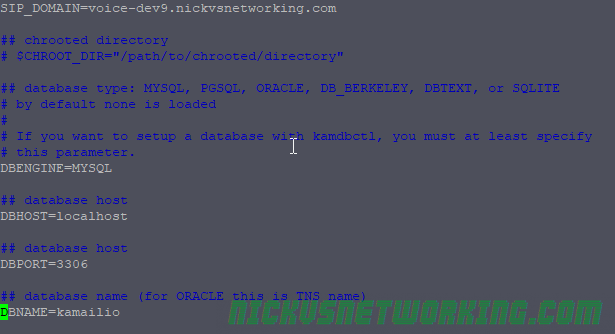
Next we’ll want to configure the file called kamctlrc in which we’ll add our database information so command line tools like kamcmd and kamctl can read and write from the database Kamailio is using.
vi /etc/kamailio/kamctlrc
We’ll need to set a few values, the SIP_DOMAIN, DBENGINE, DBHOST, DBNAME and DBPORT.
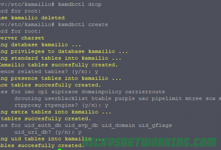
Next we’ll use the kamdbctl tool to create the database and tables required for Kamailio’s database driven modules.
kamdbctl create
Assuming you haven’t set a root password for MySQL you can just hit enter to leave it blank.
Next we’ll define a variable (AVP) in our Kamailio config file containing our database information. This means we only have to define it once and for each module we load we can just call this variable instead of defining our MySQL database information over and over again in the config.
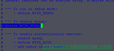
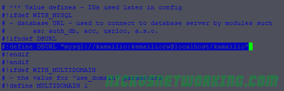
In the default config we’ll define WITH_MYSQL to use MySQL database config:
#!define WITH_MYSQL
That’ll automatically put the DBURL line into play:
And we’re done, now we can call different modules that have database functionality and start using it, some examples:
Implementation varies from module to module but you’ll have created the database tables and should be good to go implementing modules with database functionality.
If we were to take the password password and hash it using an online tool to generate MD5 Hashes we’d get “5f4dcc3b5aa765d61d8327deb882cf99”
If we hash password again with MD5 we’d get the same output – “5f4dcc3b5aa765d61d8327deb882cf99”,
The catch with this is if you put “5f4dcc3b5aa765d61d8327deb882cf99” into a search engine, Google immediately tells you it’s plain text value. That’s because the MD5 of password is always 5f4dcc3b5aa765d61d8327deb882cf99, hashing the same input phase “password” always results in the same output MD5 hash aka “response”.
By using Message Digest Authentication we introduce a “nonce” value and mix it (“salt”) with the SIP realm, username, password and request URI, to ensure that the response is different every time.
Let’s look at this example REGISTER flow:
We can see a REGISTER message has been sent by Bob to the SIP Server.
REGISTER sips:ss2.biloxi.example.com SIP/2.0
Via: SIP/2.0/TLS client.biloxi.example.com:5061;branch=z9hG4bKnashds7
Max-Forwards: 70
From: Bob <sips:[email protected]>;tag=a73kszlfl
To: Bob <sips:[email protected]>
Call-ID: [email protected]
CSeq: 1 REGISTER
Contact: <sips:[email protected]>
Content-Length: 0
The SIP Server has sent back a 401 Unauthorised message, but includes the WWW-Authenticate header field, from this, we can grab a Realm value, and a Nonce, which we’ll use to generate our response that we’ll send back.
 SIP/2.0 401 Unauthorized
Via: SIP/2.0/TLS client.biloxi.example.com:5061;branch=z9hG4bKnashds7     ;received=192.0.2.201
From: Bob <sips:[email protected]>;tag=a73kszlfl
To: Bob <sips:[email protected]>;tag=1410948204
Call-ID: [email protected]
CSeq: 1 REGISTER
WWW-Authenticate: Digest realm="atlanta.example.com", qop="auth",nonce="ea9c8e88df84f1cec4341ae6cbe5a359",     opaque="", stale=FALSE, algorithm=MD5
Content-Length: 0
The formula for generating the response looks rather complex but really isn’t that bad.
Let’s say in this case Bob’s password is “bobspassword”, let’s generate a response back to the server.
We know the username which is bob, the realm which is atlanta.example.com, digest URI is sips:biloxi.example.com, method is REGISTER and the password which is bobspassword. This seems like a lot to go through but all of these values, with the exception of the password, we just get from the 401 headers above.
So let’s generate the first part called HA1 using the formula HA1=MD5(username:realm:password), so let’s substitute this with our real values: HA1 = MD5(bob:atlanta.example.com:bobspassword) So if we drop bob:atlanta.example.com:bobspassword into our MD5 hasher and we get our HA1 hash and it it looks like 2da91700e1ef4f38df91500c8729d35f, so HA1 = 2da91700e1ef4f38df91500c8729d35f
Now onto the second part, we know the Method is REGISTER, and our digestURI is sips:biloxi.example.com HA2=MD5(method:digestURI) HA2=MD5(REGISTER:sips:biloxi.example.com) Again, drop REGISTER:sips:biloxi.example.com into our MD5 hasher, and grab the output – 8f2d44a2696b3b3ed781d2f44375b3df This means HA2 = 8f2d44a2696b3b3ed781d2f44375b3df
Finally we join HA1, the nonce and HA2 in one string and hash it: Response = MD5(2da91700e1ef4f38df91500c8729d35f:ea9c8e88df84f1cec4341ae6cbe5a359:8f2d44a2696b3b3ed781d2f44375b3df)
Which gives us our final response of “bc2f51f99c2add3e9dfce04d43df0c6a”, so let’s see what happens when Bob sends this to the SIP Server.