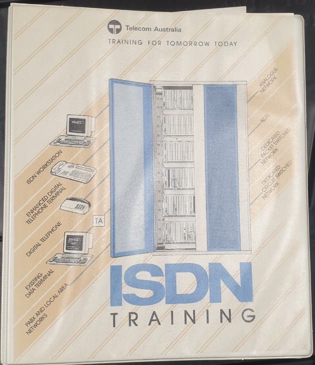
Recently, ACMA / Communications Alliance updated the rules defining cabling – S009 – “Installation requirements for customer cabling” aka the “Wiring Rules” or “Cabling Bible”.
I don’t talk much about cabling on this blog – but I’m still a registered cabler so need to keep up to date on the changes, and quite a lot has changed since the last update in 2013 – Authority to Alter (A2A) has moved from Telstra to NBNco, PayTV over HFC is far less common, and the NBN rollout is “finished”.
So what are the key changes I need to know about? I had a read and compared to S009 / 2013, and here are they are:
“Supervised” Definition
In order to gain cabling registration you need 360 hours of supervised cabling experience. The specification has been updated to define exactly what supervised means,
4.2.59 instructed person a person instructed or supervised by a Skilled Person as to energy sources and who can responsibly use equipment safeguards and precautionary safeguards with respect to those energy sources. Note: Supervised, as used in the definition, means having the direction and oversight of the performance of others.
ES3 (Electrical energy source class 3 (ES3)) Definition & Rules
Reverse power feed, used in NBN FTTC tech, as well as higher voltages used for EWIS and PA systems, has led to the introduction of a new classification – ES3, for cabling that exceeds the ES2 limits,
a metallic circuit utilised for communications or Power Feeding, or both, that— (a) exceeds the ES2 voltage and touch current limits; (b) does not exceed 400 V d.c. between conductors; and (c) does not exceed current as specified in AS/NZS 11801.1 or ISO/IEC 11801-1.
4.2.45 ES3 generic circuit
ES3 falls into two categories, which specific whether it can be carried over generic cabling or not,
(a) over Generic Cabling, in this Standard, are based on— (i) circuit voltage not exceeding 400 V d.c. between conductors; and (ii) circuit current not exceeding that specified in AS/NZS 11801.1 or ISO/IEC 11801-1. Where voltages and currents exceed these limits, then Special Application Cabling, as classified in Item F.2(b), should be used. (b) over Special Application Cabling in this Standard, are based on a voltage limit and current limit set by Cable manufacturer for the specific Cable and its installation requirements
F.2
So if part a is exceeded, Special Application cabling is required;
the cabling must meet a higher standard defined for ES3
must be identified by it’s sheath colour and markings at regular intervals
cabling has to be separated from other services (sub-ducted or separated by a barrier or more than 150mm)
must carry a warning label wherever the conductive part of the circuit is exposed (frames / joints) stating it is an ES3 service
service may not be terminated on a plug if the plug may have exposed contacts (requires a plug / socket with shutters)
an equipment circuit within the ICT Network not connected to Mains power, intended to supply or receive DC power at voltages exceeding the limits of ES2, and on which transient overvoltages or overcurrents may occur.
4.2.85
Examples are PoE, ring current, USB-C / USB3, etc.
RFT circuits are classified as ES3 circuits and subject to the same conditions.
New Conductor Size / Temperature Recommendations
S009 / 2013 did not specific recommended (not mandated) size & temperature rating for generic cabling / jumpering.
It comes down to:
“have a maximum conductor resistance of 0.0938 Ω/m at 20° C “ and “the cable should not be installed in a manner that may cause the maximum operating temperature rating of the Cable to be exceeded.”
5.6.2
Plug Terminated Cabling Requirements
Moveable cabling / plug terminated cabling must not be used unless:
the Plug is an integral part of a device that is fastened to a wall, floor or ceiling or other permanent building element; or (b) the Plug is not fixed and— (i) the Plug terminates a section of Movable Cabling; (ii) the Plug is to mate with a Port on an item of fixed Customer Equipment; and (iii) in every position to which it may be moved when the Plug is not mated with the Port, every part of the section of Movable Cabling is either out of Arm’s Reach or housed in a Secure Enclosure that is fastened to a wall, floor or ceiling or other permanent building element.
5.9.1
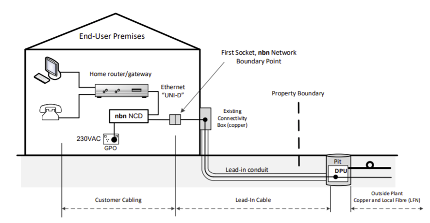
Network Boundary Definition Update
A new Appendix (J) has been added with updated (informative only) definitions of Network Boundaries with examples, to support all the new network boundary definitions introduced with the access technology mix(fibre, HFC and wireless terminations).
FTTC Deployment Information (Informative)
A new Appendix (O) has been added providing information in regards to FTTC and it’s requirement to isolate the first socket from the rest of the cabling – Something that in practice seems to be a rarity.
Labelling & Safety Rules for Fibre Optic Cabling
A new requirement has been added to 11.1 in regards to Fibre Optic cabling must:
Have a Warning of potential hazardous laser levels
Have a warning regarding Access to emitted radiation
Types of laser warning markings
Laser warning marking style
Laser explanatory label wording
Marking durability of labels
Fibre outlets in work areas are except
Groups of optical fibre connectors may be marked as a group
Multiple markings – ie one inside the container one outside
Unused optical fibre connectors and adaptors must be covered
I’m a bit of a radio nerd & I’ve worked Satellites before, so the Skymuster / LTSS program had me curious. So here’s some nitty-gritty details on NBNCo’s Skymuster Satellite service.
The Payload
NBNco called the LTSS (Long Term Satellite service) but before launch they re-branded as “Skymuster”.
NBNco provided an Interim service called ISS (Interim Satellite Service). before the launch. IPSTAR satellite (Formerly ABG) and Optus services delivered this. Both of these had limited bandwidth and has since been largely replaced by the Skymuster / LTSS.
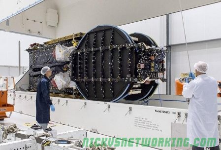
NBNCo contracted Space Systems / Loral, a US based satellite manufacturer to design and build the payloads. It’s based on the SSL 1300 platform.
When deployed, the payload itself measures 26 metres long, 9 metres tall and 12 metres wide, and weighs in at 6400Kg. Before deployment, in the satellite’s compressed form it fits within a 5-meter launch-vehicle fairing.
Communication to earth is via Ka-band frequencies which allows for greater density of spot beams and frequency reuse. However, capacity improvement through higher frequencies does come with some tradeoffs. Ka-band frequencies, are more susceptible to weather related conditions compared to Ku-band frequencies. Directional accuracy becomes way more important when aligning the customer dishes in Ka band also.
SSL provided image of SL-1300
Direction
Min Freq
Max Freq
Earth to Satellite
27Ghz
31Ghz
Satellite to Earth
17.7Ghz
22Ghz
These emissions are within the range of the higher end software defined radio receivers. I’m curious to see what’s being transmitted, but that’s a topic for another day.
The downlink uses RH and LH circular polarisation.
The Journey
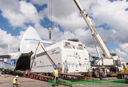
SSL assembled the satelite in California.
SSL staff packed it into a crate and loaded into the belly of an Antinov An-124 which is flown to the launch site.
There are two Skymuster Satellites, NBN-Co 1A & 1B. 1B provides infill / capacity layer for 1A but both are identical. If the 1A satellite was lost during launch / deployment, 1B could be sent up in it’s place. This is still a real risk when launching anything.
NBN-Co 1A was the first launched, riding on a Ariane-5ECA from Guiana Space Centre in French Guiana, South America. 1A launched on 30.09.2015 and 1B launched 05.10.2016 in the same configuration.
After launch to a transit orbit, the satellites had to navigate up into a geostationary orbit at ~36,000Km. This was done using it’s 4 × SPT-100 plasma thrusters, which are exactly as cool as they sound. The final navigation process took up 40% of the fuel in the satellite. Fuel is the determining factor for the expected ~15 year lifetime of the two satellites.
SPT-100 – Source: NASA
Once in final position SSL performed 2 months worth of tests referred to as “In Orbit Testing”. SSL then handed over operational Telemetry, Tracking and Command (TT&C) to Optus Satellite (Singtel). Optus are tasked with keeping it in it’s current position.
Customer Hardware
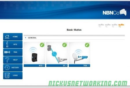
Ericsson manage the installation, and subcontract to Hills and Skybridge for the actual work.
Out Door Unit (ODU)
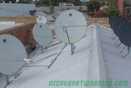
There are currently 3 Satellite Antenna options that are available for installation, 80cm, 1.2m & 1.8m.
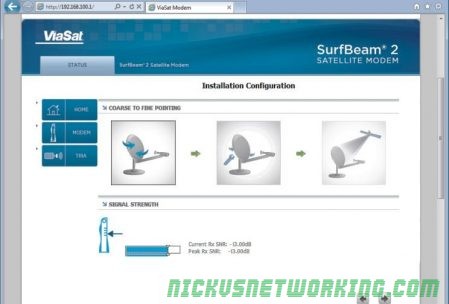
NBNco’s Test Setup
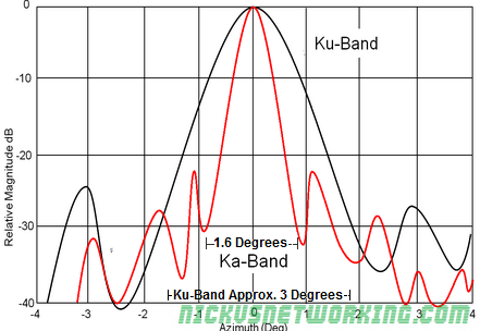
Narrower Ka-Band signals drops off more rapidly than Ku-Band signals. This means that aligning the Ka-Band antenna within the degrees of usable Azimuth within the Line of Sight maximises the antenna gain.
Required accuracy for each of the antennas:
80 cm: 1.4 degrees,
120 cm: 1.0 degrees
180 cm: 0.7 degrees
The below graph shows being off by 1 degree from the required accuracy, leads to -30dB drop. This translates to a power ratio of 1000, or 1/1000 of the power if correctly aligned.
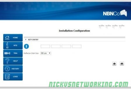
The alignment process is done by the installer pointing the dish in the correct azimuth / elevation. This is based on compass / inclinometer readings, or smart phone apps. Once a rough alignment has been set, a tone-generator on the TIRA is used to align the dish.
This process requires a 16 digit installation key.
The key containing the frequency used in the installation, beam Assignment & TRIA Polarisation (The 6w version has automatic (Polarisation).
That’s entered into the installation setup page at:
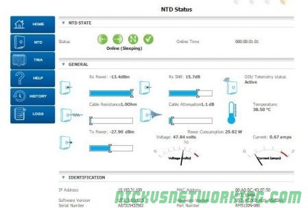
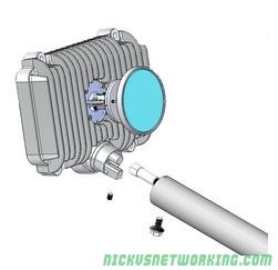
The TRIA is the equivalent of a feed horn, an all in one Tx/Rx assembly. They are available in 3w and 6w variants, based on the estimated signal levels of the installation location. That’s determined by factors like high rain areas or if the subscriber is on the edge of a beam.
3W Version
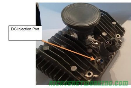
The 6W version has an extra F-Connector for the required DC power injection. The 6w version also has a two F-Connector gang-plate / wallplate when installed for the second RG6 run to power it.
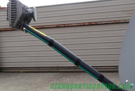
Interestingly there’s a minimum length of cable run (8m) specified for these installations. Anything less than 8m leads to lower resistance and possible overheating.
There is a minimum length of 8m for the cable run this is very important as it provides the right amount of cable resistance so the modem does not get hot and over heat. Max cable run is 50m.
Configuration
Transparent Performance Enhancing Proxy (TPEP)
TPEP aka Web Acceleration, is a service offered by NBNco to spoof TCP replies, to make the handshake more efficient. It can, unsurprisingly, lead to headaches accessing services, particularly those that employ TLS.
The installer key sets the beam, and his can be remotely changed by NBNco MAC / NOC team.
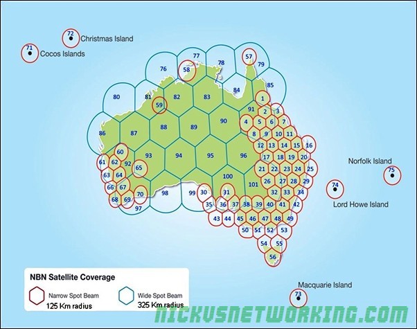
BIRRAUS have a good article explaining the spot beams available.
Educational Port
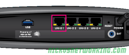
Like the other NBNco NTDs, there are multiple UNI-D ports available on the Skymuster modem allowing segregation of services.
One option that seems to be gaining traction is a dedicated port on the modem for educational use, on one of the UNI-D ports on the modem.
Educational Ports are configured to allow access for remote / distance education students.
The local state government sets pricing, speeds and data usages.
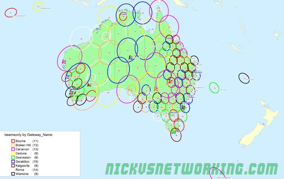
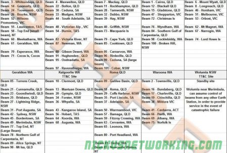
Ground Stations
There are 9 active and one standby ground stations, geographically spread across Australia, with a standby in Wolumna, NSW. The standby is capable of assuming control for any of the other ground stations.
ViaSat built the equipment and services different spot beams.
Again, BIRRAUS have this covered in their article, but here’s an extract they’ve made listing the ground stations and beams serviced.
Wolumla ground station
Future
Solar Transit
Solar transits happen twice yearly when the satellite is aligned directly between the sun and Australia.
The immense solar radiation from the sun overloads the transceivers on the ground, as they’re positioned at the satelite, with the sun behind it overloading the signals.
This lasts for about 6 minutes twice yearly, and affects different ground stations and each of the satellites at different times.
Copper Cutoff
Currently the copper decommissioning does not apply to Skymuster services. This means customers with a copper POTS line, can keep it indefinitely.
This has lead to headaches with incumbent providers who had intended to decommission / sell off remote exchanges, but will be required under Universal Service Obligation to keep them active.
3rd Satellite
Due to unexpectedly large uptake of Skymuster services, NBNco had floated the possibility of launching a 3rd Satelite in 2020:
Scenario 3: Third satellite – This scenario assumes that NBN Co constructs and launches a third satellite at the end of CY20. This mitigates the need to build some fixed wireless base stations and FTTN distribution areas. The capacity of this satellite will only be partially required to meet NBN Co’s needs
Scenario 4: Third satellite in partnership – This scenario mirrors Scenario 3, but assumes that NBN Co enters into a partnership with an external party to access only the required capacity on a third satellite rather than building and owning it outright.
The NBNco launched a fleet of “Road Muster” 4WDs for promotion of the services. They drive from town to town, spruiking the benefits of Skymuster.
On the roof of the 4WD is a Satellite ODU, which seems to be self / remote positioning.
Online sleuthing reveals it’s a EXPLORER 8120 manufactured by Cobham. It featuring auto-acquire, drive-away antenna system using Dynamic Pointing Correction technology. At $32k USD, it’s rather pricey, and outside the range of most grey-nomads and campers.
If a user wanted to manually position the dish, they could using a service like DishPointer.com or Wolfram Alpha. This would give a rough alignment and then the tone generator “Point and Peak” for the fine adjustment.
Layer 3 Services
Skymuster services are setup as L2 services.
NBNCo has highlighted from day 1, the option of using Layer 3 for deliver to enable deep packet inspection.
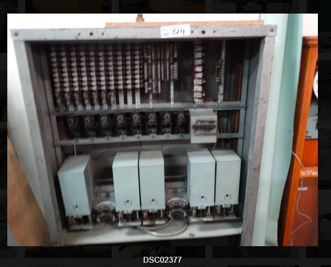
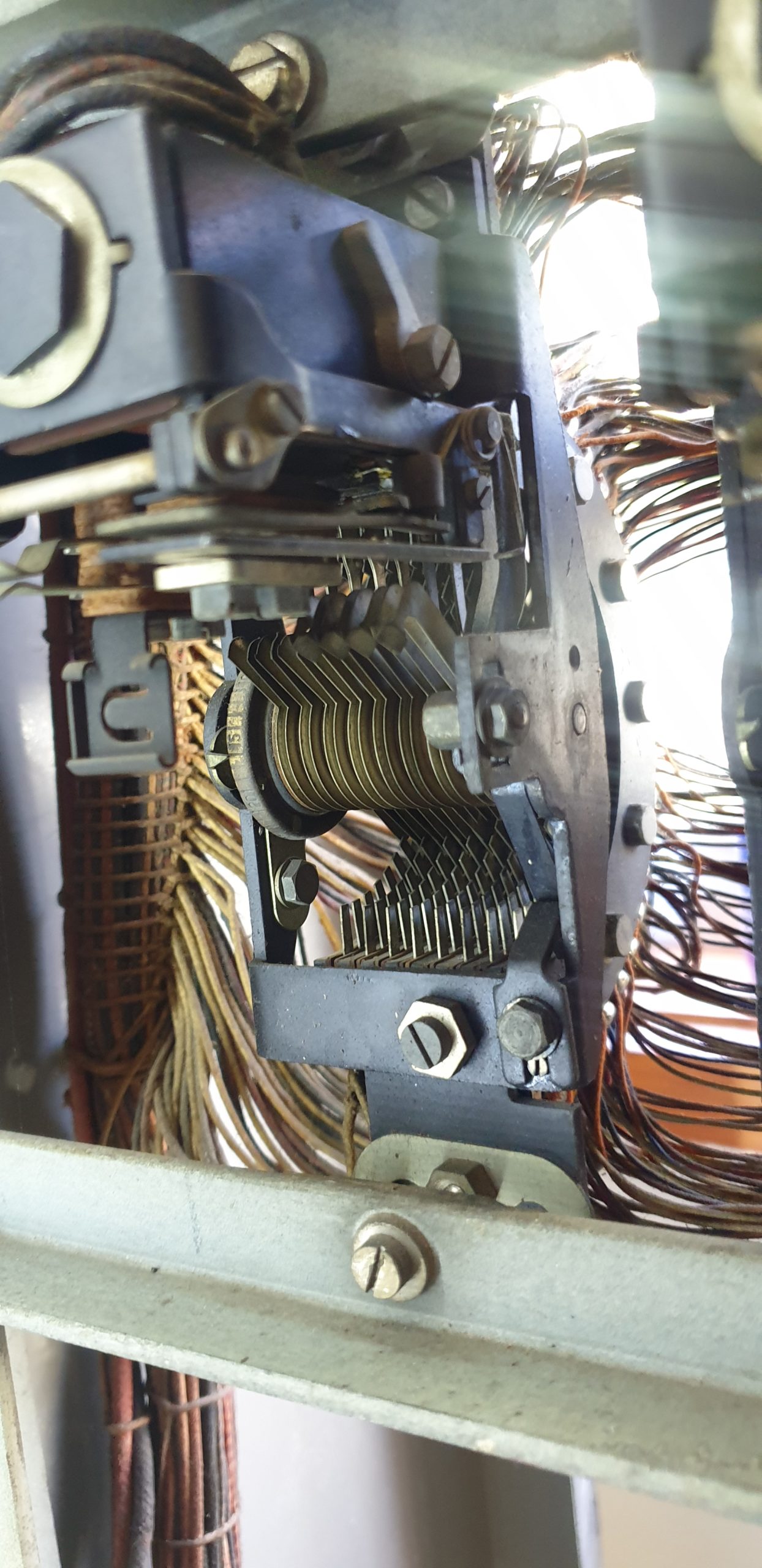
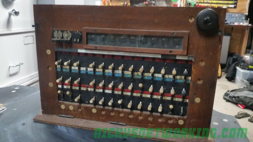
The blurry photo didn’t make anything that much clearer, but they looked like two motion switches, and being a big fan of really old telco hardware, I found myself driving to an auction selling things very much unrelated to telephone exchanges to bid on what I thought might have been a step-by-step exchange.
Photo from listing
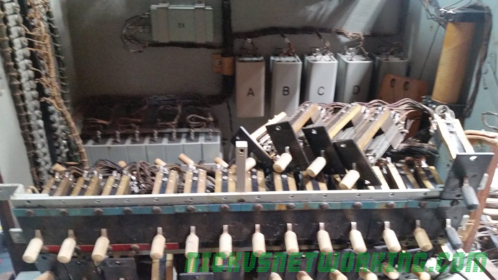
$50 later I am now the proud owner of an Automatic Telephone & Electric Co (ATE) Liverpool works 50 line PAX (Private Automatic Exchange).
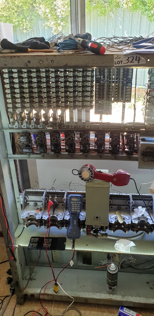
The switch
My office now has less room, a big burly battery eliminator and ring machine take up the space on my desk, but I couldn’t be happier with it.
Uniselectors
Of the 5 final selectors I’ve got two somehow worked “out of the box”, while the other 3 all need some serious adjustment, but she clicks and she’s mostly complete, so should be a good summer holiday project!
I’ll post some video up when she’s fully functional.
There’s always a lot of talk and opinion about the technologies the NBN employs, it’s effectiveness, etc.
I’ve made a conscious decision to steer clear of opinion in this blog, but there’s often talk and blame shifting between NBNco and RSPs, so I thought I’d cover how the business model works.
Because of this I thought it’d be interesting to write about how the network actually works between carriers (RSPs) and NBNco.
Physical Structure
Last Mile
The last mile in US terms, CAN in Australian Telecom lingo, is connecting the subscriber edge to the network.
NBNCo employs a few different technologies for this, depending on a number of factors;
Fiber to the Premises (Original standard – End to end fibre)
All these last mile services get consolidated and eventually end up at a local PoI – Point of Interconnect, (typically called a POP if you’re any other telco).
These are typically hosted inside exchanges, but not every exchange is an NBNco PoI, if it’s not it uses NBN Backhaul to get to the nearest PoI.
NBNco currently operates 121 PoI sites.
NBNco don’t exclusively use TEBA sites, some are hosted in NBNco “Depots”, there’s currently 10 sites not in TEBA footprints.
At the PoI
Retail Service Providers (RSPs) have to have racks inside the PoI locations, and essentially setup layer 2 cross-connects to the NBNco racks.
Once the traffic is on the RSP network, it’s the RSP’s responsibility to carry it where it needs to go, via their own network / backhaul.
Billing and Metering
Of course, if NBNco is handing off the pipes of customer traffic off to each RSP they need a way to charge the RSPs for this, this is handled by two elements – CVCs equating to the bandwidth at the PoI and AVCs equating to a fixed standing charge per connection monthly.
CVC – Connectivity Virtual Circuit
At the PoI the connection between the NBNco rack and the RSP rack is metered over a CVC – Connectivity Virtual Circuit.
This is shared across all users of that RSP at that PoI.
Let’s say I’m an RSP and I’ve purchased a 1Mbps CVC shared across my 1,000 customers at that PoI, the customers aren’t going to have a good experience.
Of course, CVC bandwidth isn’t free, previously NBNco charged on average $15.25/Mbps.
This had the effect of ensuring each RSP had just enough CVC bandwidth for their customers, but this led to some customers having a poor experience on switching to NBNco as they found their speeds dropped due to not enough CVC bandwidth at the PoI for that RSP.
In June 2017 NBNco announced a change to the pricing structure to try and encourage RSPs to buy more CVC bandwidth to ensure customers speeds weren’t bottlenecked at the CVC.
The new pricing structure makes it more financially attractive to buy more CVC bandwidth based on how many active connections (AVCs) an RSP has in place.
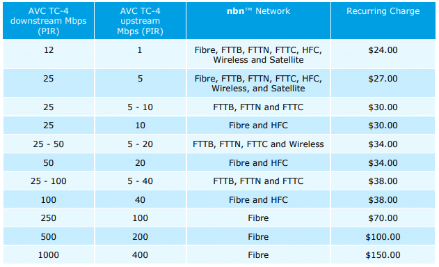
NBNco now charges $17.50 per symmetrical Mbps for each traffic class. (More on traffic classes later)
This means at each PoI the RSP must have a pool of CVC bandwidth large enough to meet the needs of all the customers connections (AVCs) bandwidth needs at that PoI.
AVC – Access Virtual Circuit
NBNco charges AVC fees based on the speed tier the end user will have and the traffic class (QoS) the service has applied.
(This speed tier is regardless of if the RSP has the CVC bandwidth to support this)
Pricing of TC4 (Best Effort) AVCs
Introducing NNIs
NBNco acknolged in Jul 2018 that for some carriers (RSPs) having presence in 121 sites puts up a large barrier to entry.
To counteract this they introduced Network-Network Interface (NNI).
Imagine you’re operating an RSP with a footprint in capital cities and PoI / CVCs in populated areas, you can’t serve customers in remote areas without having a presence at their local NBNco PoI location and buying CVC bandwidth for that location – It just wouldn’t stack up financially.
NBNco introduced the NNI product to essentially backhaul the traffic from these customers to the nearest PoI their RSP is at and share the CVC bandwidth at that PoI.
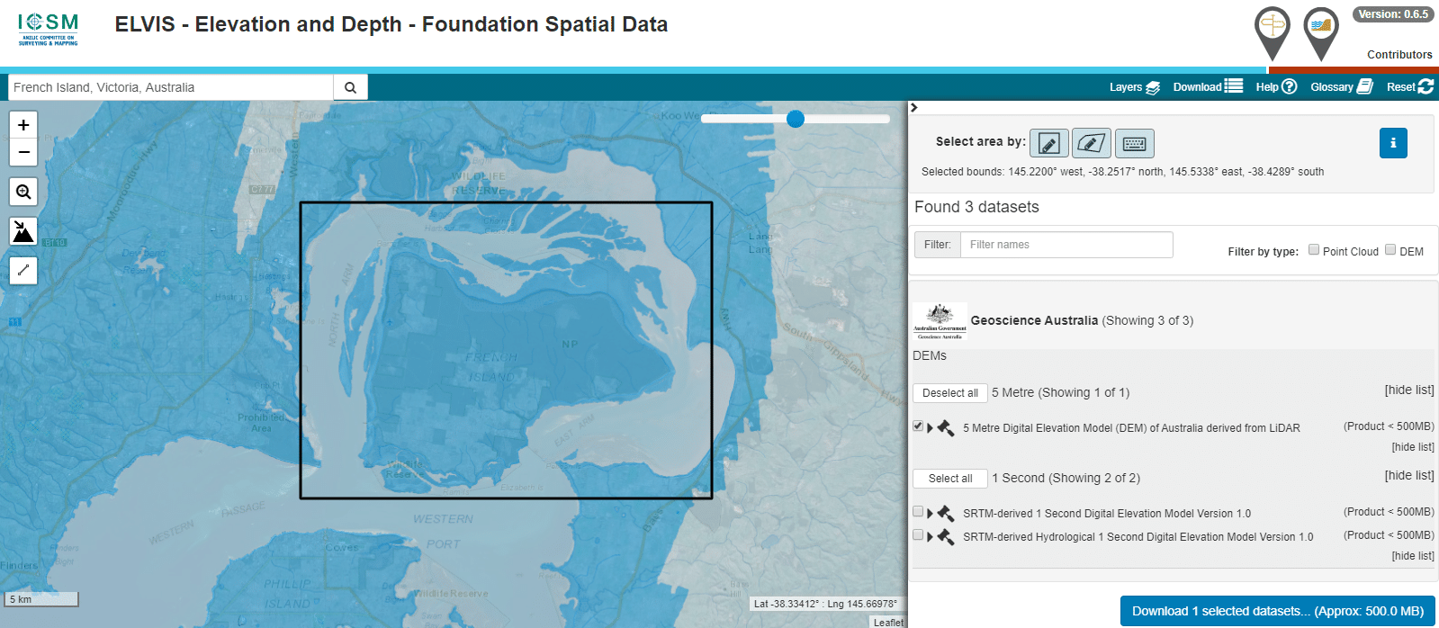
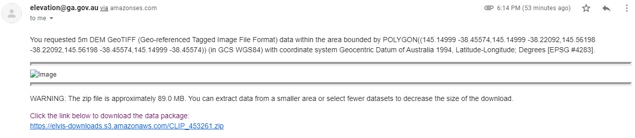
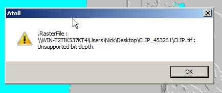
The Australian Government publishes elevation data online that’s freely available for anyone to use. There’s a catch – If you’re using Forsk Atoll, it won’t import without a fair bit of monkeying around with the data…
You draw around the area you want to download, enter your email address and you’re linked to a download of the dataset you’ve selected.
So now we download the data from the link, unzip it and we’re provided with a .tiff image with the elevation data in the pixel colour and geocoded with the positional information.
Problem is, this won’t import into Atoll – Unsupported depth.
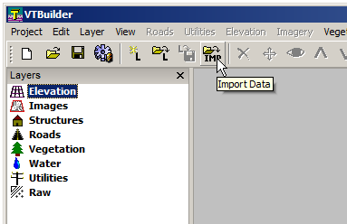
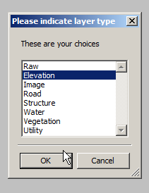
I fired it up, and imported the elevation tiff file we’d downloaded.
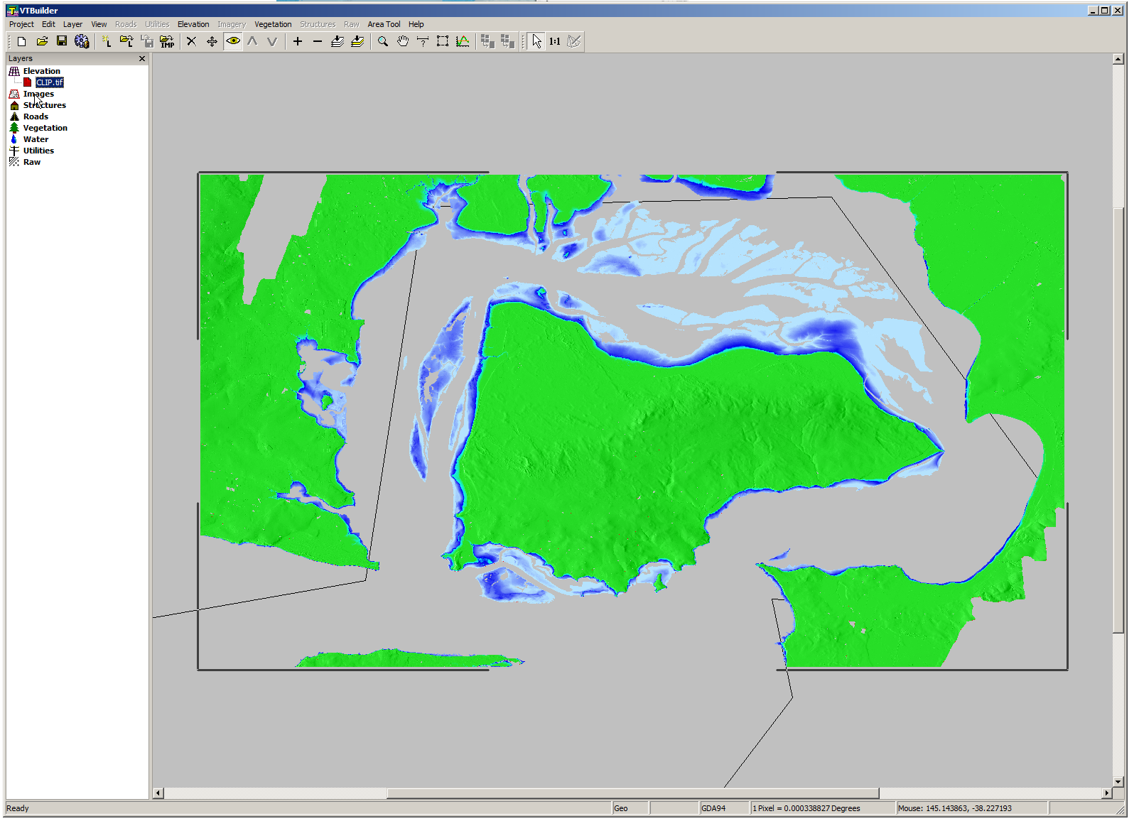
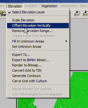
Selected “Elevation” waited a few seconds and presto!
We can export from here in the PNG 16 bit grayscale format Atoll takes, but there’s a catch, negative elevation values and blank data will show up as giant spikes which will totally mess with your propagation modeling.
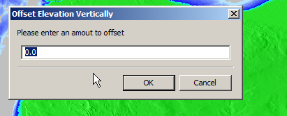
So I found an option to remove elevation data from a set range, but it won’t deal with negative values…
So I found another option in the elevation menu to offset elevation vertically, I added 100 ft (It’s all in ft for some reason) to everything which meant my elevation data that was previously negative was now just under 100.
So if an area was -1ft before it was now 99ft.
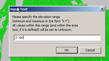
Now I was able to use the remove range for anything from 0 100 ft (previously sea level)
Now my map only shows data above sea level
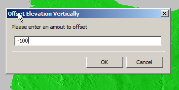
Now I offset the elevation vertically again and remove 100ft so we get back to real values
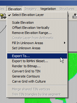
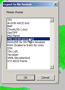
Now I was able to export the elevation data from the Elevation -> Export to menu
Atoll seems to like PNG 16 bit greyscale so that’s what we’ll feed it.
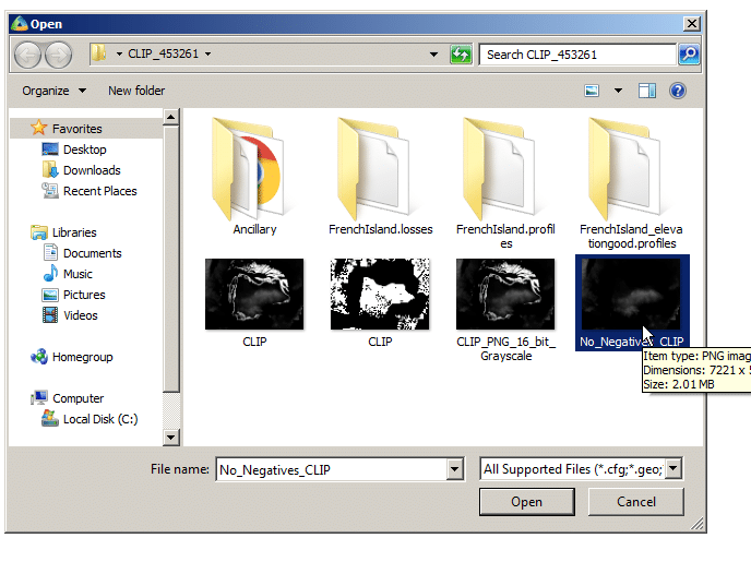
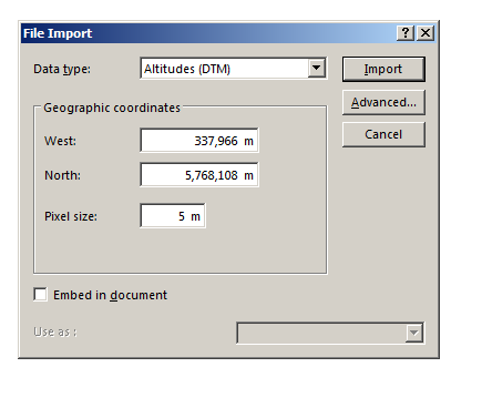
In Atoll we’ll select File -> Import and open the PNG we just generated.
Data type will be Altitude, Pixel size is 5m (as denoted in email / dataset metadata).
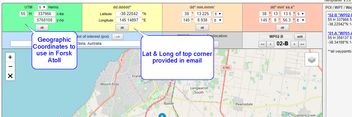
Next question is offset, which took me a while to work out…
The email has the Lat & Long but Atoll deals in WGS co-ordinates,
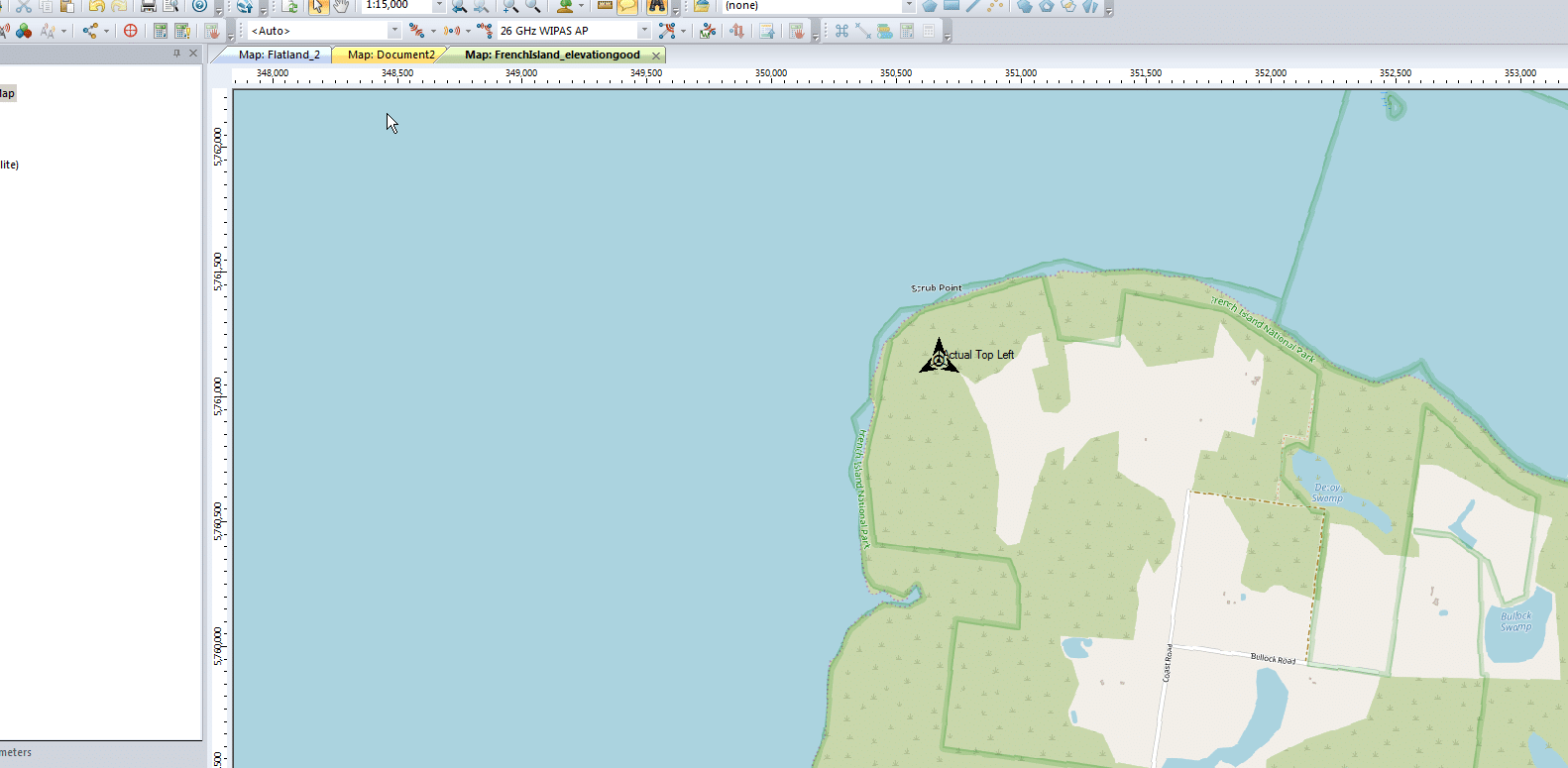
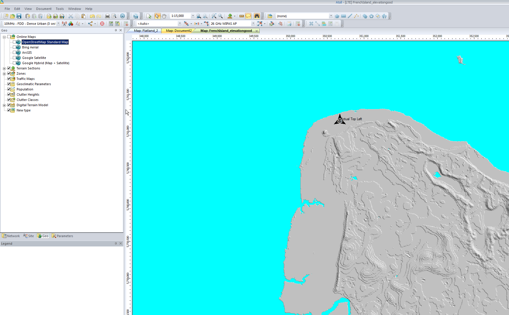
Luckily the GeoPlanner website allows you to enter the lat & long of the top corner and get the equivalent West and North values for the UTM dataum.
Enter these values as your coordinates and you’re sorted.
I can even able a Map layer and confirm it lines up:
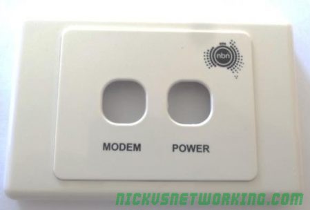
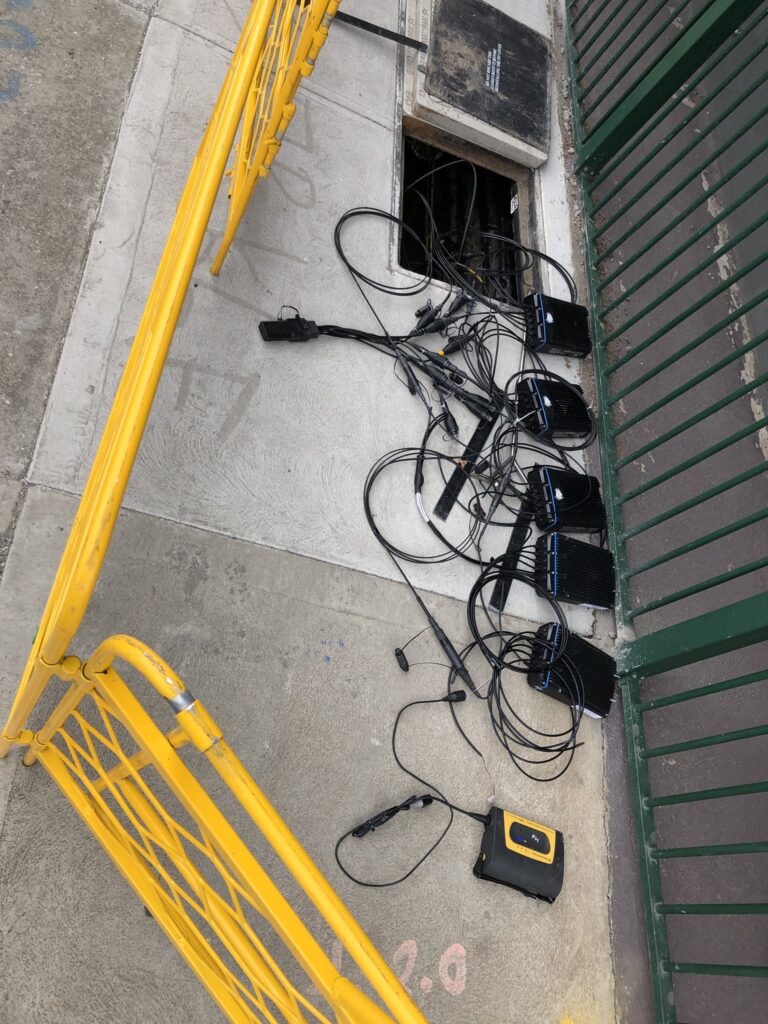
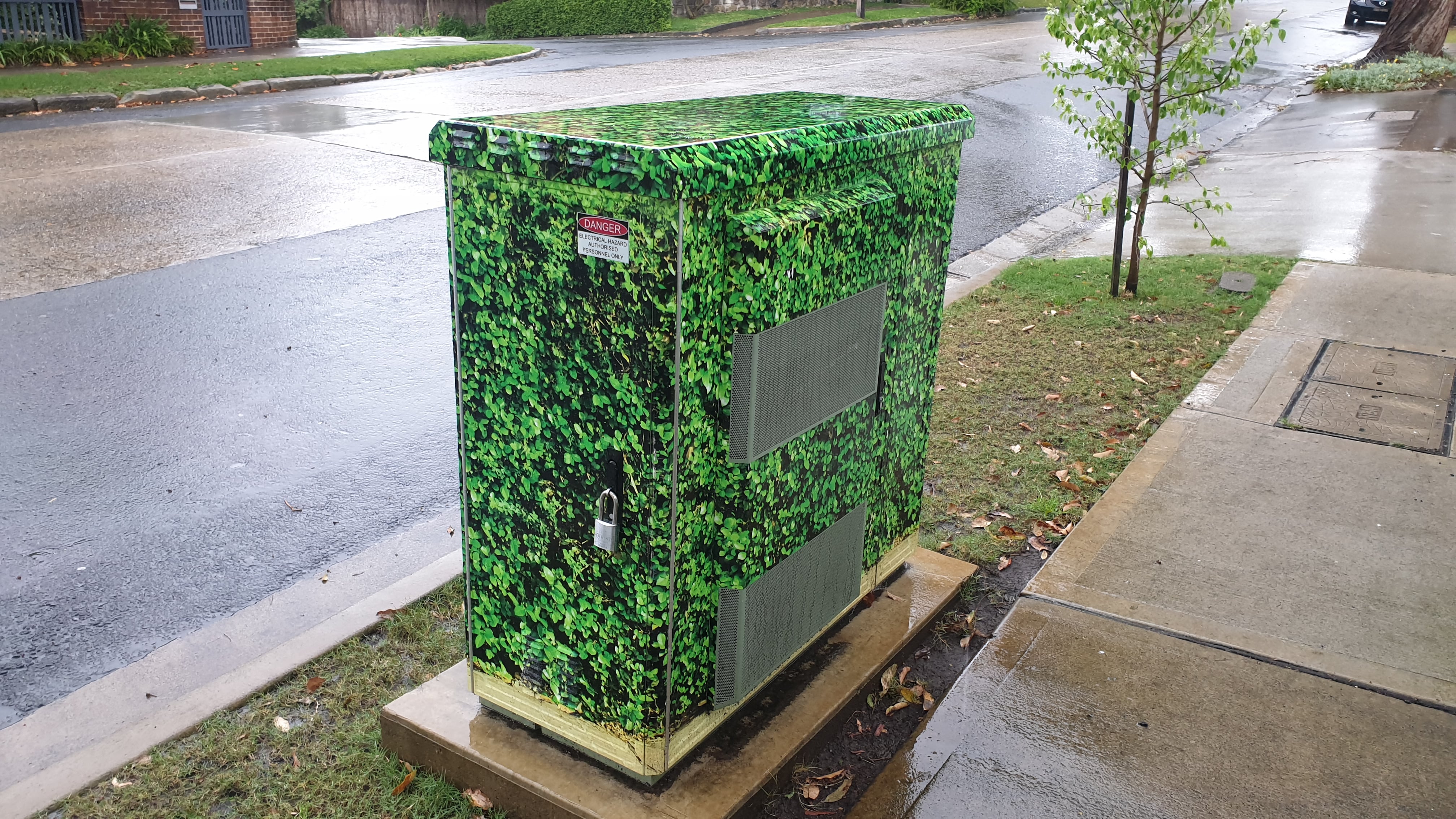
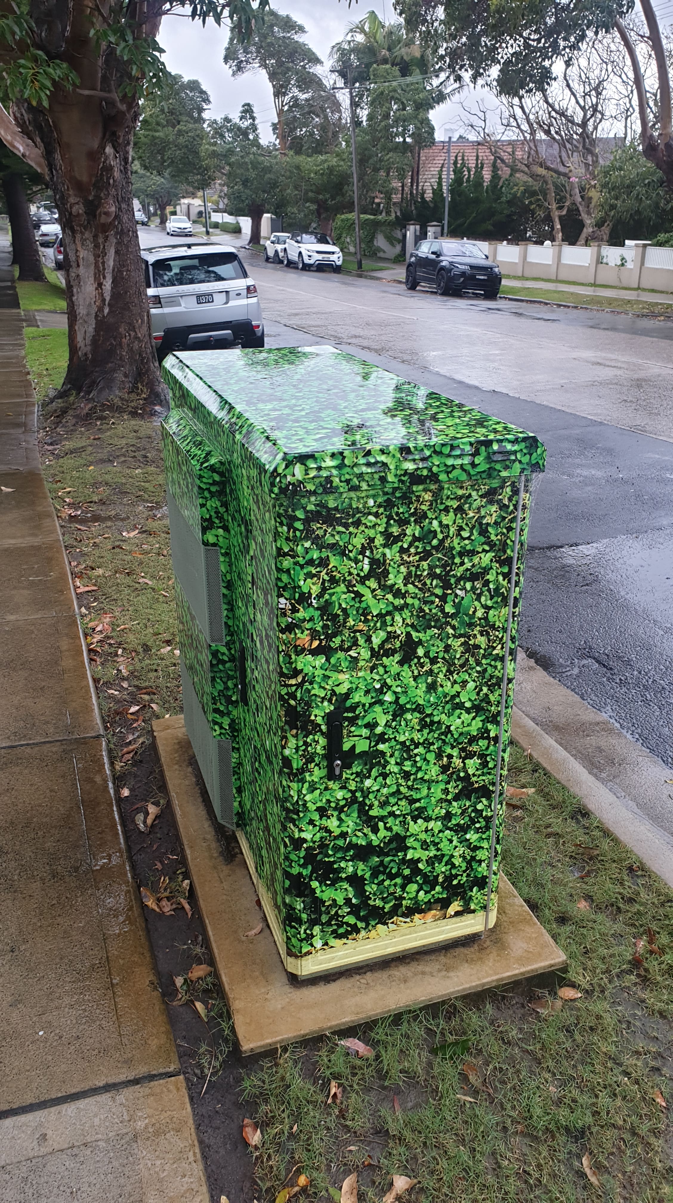
NBNco’s FTTC technology is accounting for a larger and larger share of the access network mix as the rollout nears completion, but let’s take a look at the hardware doing the heavy lifting.
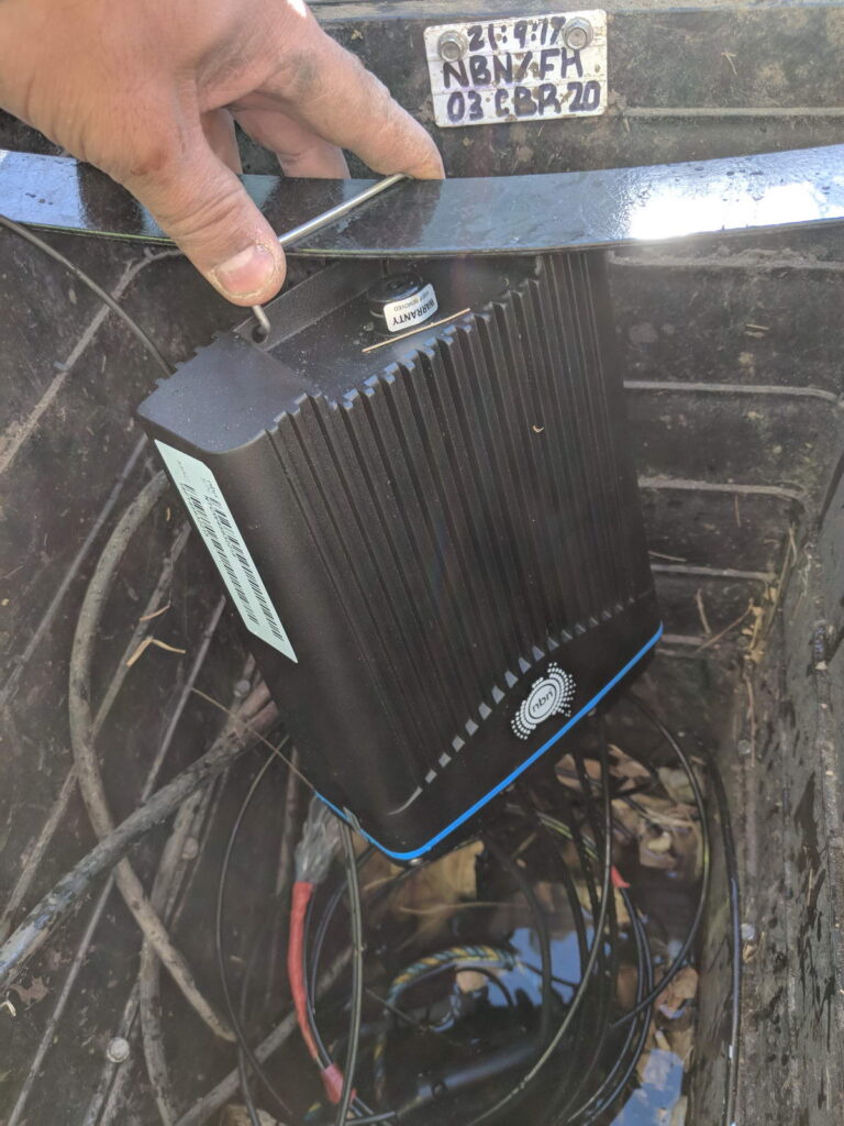
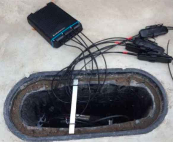
I won’t go into the fiber network build NBNco are using (Squids, etc) in this post, we’ll just focus on the DSLAM that lives in the pit outside your house, or in NBN parlance – DPU or Distribution Point Unit.
In short, this is a 4 port DSLAM, fed by a fiber service and reverse powered.
The unit itself is waterproof, allowing it to live in the pit outside a customer premises, for FTTC deployments it’s common for every second P3 pit to contain a DPU (each pit typically feeds two premises).
There’s 4 copper tails for connecting in each of the 4 copper pairs to feed 4 premises. The copper run is typically less than 100m and is pretty easy to work out – Pace the distance from your first telephone outlet (TO) to your nearest pit, and there’s a 50% chance that’s the length of your cable run. Because of the short run of cable it’s a lot less to go wrong in the CAN, the only joint on the pair being the one on the DPU itself and anything inside the demarcac.
The DPU is powered by the customer’s modem via a reverse power feed, this means NBNco don’t have to worry about powering the unit, something on FTTN cabinets has been a maintenance headache due to battery backup maintenance.
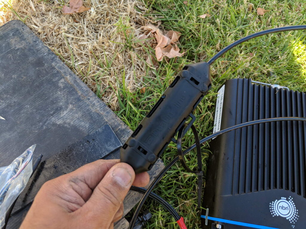
The lead in cable to the customer premises is joined to the DPU via a “Snot Box”.
Snot box for joining lead in to DPUDPU in the pit
Unfortunately due to the enclosures being water tight and sealed, they don’t have the best thermal management. It’s not uncommon for them to reach 50+ degrees C in the field, which leads to a high failure rate, especially during summer.
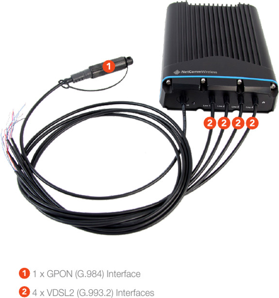
NetComm Wireless / Casa NDD-4100
In 2016 NetComm Wireless (Now owned by Casa Systems) signed an agreement with NBNco to provide Fiber to the Distribution Point (FTTdp) Distribution Point Unit (DPU) equipment to NBNco for the launch in 2018, using their NetComm NDD-4100 units.
The unit has 4 ports for customer connections over a VDSL G.9923 interface, with reverse power feed, meaning the unit is fed by the CPE.
For backhaul the unit has GPON G.984 interface.
The device may not be powered at all times so a management proxy caches commands that are fed to the system when it comes back online.
Promo video
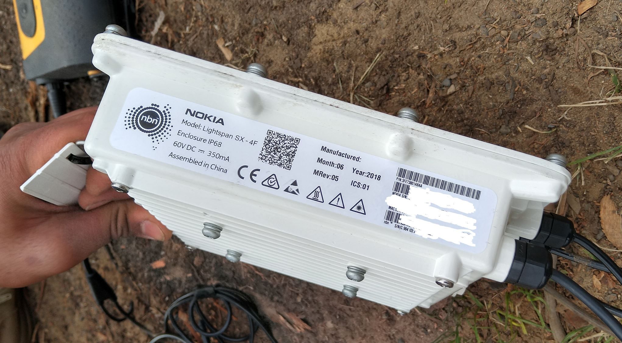
Nokia lightspan sx-f
In June 2018 NBNco started trialing Nokia DPUs, and many later installations since then are using the Nokia DPU.
I’ve head a bunch of complains about the NetComm having issues and dying, and for a sealed unit there’s very little debugging that can be done to it.
In the Melbourne office of NBNco there’s a Nokia DPU that’s been running in a fish tank for a number of years.
The numbering system lists all the phone numbers in Australia and the carrier they’re assigned to (Donor Carrier when ported).
This means each carrier downloads this data from what is now ACMA (but was at the time ACA) and for each outgoing call look the number up in that data set and route to the correct carrier.
This routing is used when a number has not been ported – The CSP it’s allocated to by ACMA is the CSP to route calls to.
During Porting – Donor & Losing CSP the Same
At the time the number is ported the Losing CSP provides Donor Transit Routing – In practice this is nothing more than a fancy redirection/ forward to the new carrier.
Once the port is completed (and the Emergency Porting Return period has expired) the Losing CSP (who in this case is also the donor CSP) updates their PLNR file, to include the number that’s just been ported out and the new carrier’s code.
During Porting – Donor & Losing CSP Different (3rd Party Porting)
At the time the number is ported the Losing CSP provides Donor Transit Routing – In practice this is nothing more than a fancy redirection/ forward to the new carrier.
Once the port is completed (and the Emergency Porting Return period has expired) the Donor CSP updates their PLNR file, to update the record for the ported number, which previously showed the code of the Losing CSP and now must show the new CSP code.
After Porting – PLNR Update
After the PLNR has been updated by the Donor CPSs, other CPS that participate in porting must update their routing records to ensure they route directly to the Gaining CSP and not to the Donor CSP and rely on Donor Routing.
Donor Routing is only required to be in place for a short time, meaning carriers that don’t update their routes will find the ported destination unreachable once donor transit routing has been stopped.
Why am I still billed after a number is ported out?
The Losing CSP does not need to take any action to disconnect Customer’s Telephone Number(s).
3.4.3
This means just porting out a number from a CSP doesn’t mean billing from the Loosing CSP will stop.
Continuing contractual agreements between the customer and Loosing CSP may still be in place and the customer is responsible for requesting the services be cancelled with the Loosing CSP.
Some CSPs work out that if you’re porting out a number you don’t want their services anymore, but they’re not obliged to and most will do what they can get away with.
What is a Bilateral Peering Agreement?
While a customer is legally entitled to move a number they have full control over (As outlined in Telecommunications Numbering Plan 2015), in practice phone numbers can only be moved from one carrier to another if both CSPs have a Bilateral Peering Agreement with each other.
These agreements primarily sort out the commercials of how much they’ll pay each other per port in / out.
It’s worth also noting that the Code only defines the minimum standard and process, two CSPs that have a bilateral peering agreement in place are able to process ports faster and more efficiently than the minimum standard outlined in the code.
Carriage Service Provider vs Carrier?
I’ve been sing the term Carriage Service Provider and Carrier interchangeably.
The difference as far as the code is concerned is one is who a customer pays for the service, while the other is the provider of the service. Generally it’s safe to assume that the CSP is also the Carrier and not a re-seller.
These numbers can be ported to other CSPs (this is after all what LNP is all about) but after the number is routed to a different carrier the Donor Carrier remains the carrier listed in the Numbering Plan.
The Donor Carrier is responsible for Donor Transit Routing (A temporary redirect to numbers that have been ported away recently) for any numbers that have recently been ported out, and publishing the number and new carrier details for each number ported out in their PLNR file.
These numbers can be ported to other CSPs (this is after all what LNP is all about) but after the number is routed to a different carrier the Donor Carrier remains the carrier listed in the Numbering Plan.
In a scenario where a call needs to route to a destination where the current carrier for that destination is unknown, the call is routed to the Donor Carrier, as that’s who the number is originally allocated to by ACMA.
Upon reciept of a call by the donor carrier to a number that has been ported out, the donor’s switch finds the correct Access Service Deliver (ASD) and redirects the call to them.
This is a temporary service – CSPs are only obliged to do this for 5 days, after which it’s assumed the PLNR file of the donor will have been read by all the other CSPs and they’ll be routing the traffic to the correct CSP and not the Donor CSP.
Third Party Ports
Third Party Porting is where the Donor Carrier is neither the Losing Carrier or the Gaining Carrier. Third Party Porting requires bilateral agreements to be in place between each of the parties involved.
As we just covered ACMA allocates numbers to CSPs, when a number is ported to a different CSP the number is still allocated to the original CSP as far as ACMA and The Numbering System are concerned.
The CSP the number was originally allocated to is the Donor CSP – forever.
Let’s look at a two party port first:
A number is allocated by ACMA to CSP 1
The customer using that number decides to port the to CSP 2 using the standard LNP process
CSP 1 performs Donor Transit Routing for the required 5 days and updates it’s PLNR file to denote that the number has been ported to CSP 2
Now let’s consider a three party port, carrying on from the steps above.
The Customer decides they want to move from CSP 2 to another CSP – CSP 3
At the time of the port the donor CSP (CSP 1) must:
CSP 1 must update it’s PLNR records for this number to denote it’s no longer with CSP 2 but is now with CSP 3
CSP 1 must provide Donor Transit Routing for the required 5 business days – redirecting calls to CSP 3
So even though the number is moving from CSP 2 to CSP 3 as the number was originally allocated to CSP 1, it is, and will always be the Donor Carrier and as such has to provide Donor Transit Routing and update it’s PLNR each time the number is ported.
Port Reversal / Emergency Return
Ports have an emergency return window inside which the port can be reverted. For Cat C ports this invovles the project manager of one CSP contacting the project manager for the other CSP and requesting the return.
In the event the end customer has requested the Port Reversal / Emergency return they’re typically liable for a very hefty fee to do so.
Give Back & Quarantine of Numbers
After a number is no longer required, it’s given back to the donor carrier who places it in quarantine and typically does not reallocate the number for 6 months.
In some cases such as a wronly cancelled number the customer may be able to get a number that’s been cancelled back while it’s in it’s quarantine state, however this is not required and up to the donor carrier.
Including Customer Account Numbers when Porting
Prior to 2016, a customer moving from one CSP to another CSP were required to include their account number (“Service Account Number”) they had with the Loosing CSP to the Gaining CSP when submitting the Port which was verified against the Loosing Carrier’s records to ensure the correct Customer / Service combo.
This led to a lot of ports being rejected unnecessarily due to mismatched account numbers, as such the the requirement to include a valid matching account number with the loosing CSP has been removed.
Service Account is to remain as a mandatory field, and a standard validation but any mismatches are not to be rejected.
Where’s Cat B & Cat D?
Cat B Dropped in 2013 revision due to lack of use.
Cat D is almost the same as a Cat A port but allows services with an active ULL diversion to be ported. These are quite rare and a very specific use case.
Why is my Cat C Port taking so long?
You may find after submitting a port the date you’ve got back for porting is months away. The Loosing Carrier sets the porting date, and as they’re loosing the customer, they’re often not so keen to action the port quickly when they’re loosing the customer after all.
Lead Times are determined by the Losing Carrier. These may vary by product including variations due to the size of the product or the number of sites to which a particular service is offered.
3.5.10
Tidbit: One of Australia’s largest carriers has a 20,000 number per day limit on porting, meaning they’re only able to process up to 20,000 ports per day in or out. Once that limit is reached no more ports can be accepted for that day, so the ports are delayed until the next day, etc, etc, leading to considerable lead times.
The code requires CSPs to keep Service Metrics on porting time-frames, but there’s no penalty for being slow. (Section 3.6)
Third Party ports also take a lot longer due to the requirement to find a time window that suits all 3 carriers.
Can I arrange my numbers to be Ported after-hours?
CSPs are not required to port numbers outside of the “Standard Hours” defined in the code. (Section 3.8.1 )
However, most CSPs have included support for this inside their bilateral agreements with other carriers. This typically costs more for the customer, but also comes with the added risk of if the port fails there are fewer technical / engineering resources available at the Loosing and Gaining Carrier’s respective ends to sort it out if something goes wrong.
What’s a PNO?
Porting Notification Order – A message containing either a Simple Notification Advise (SNO) for Simple (Cat A) ports, or a Complex Notification Advise (CNA) for Complex (Cat C) ports.
Each PNO contains a unique sequential reference number to differentiate / associate the PNO with a particular porting request.
PLNR – Ported Local Number Registry
PLNR is nothing more than a giant text file, containing a list of numbers originally allocated to that CSP but that have been ported to another CSP, and with each number that’s been ported out the carrier code of the CSP it’s now with.
Information to facilitate Call Routing is provided by the Donor Carrier who is required to notify Carriers, via a Ported Local Number Register, that a Port is pending, completed or did not proceed. This relates to all Ports, including Third Party Ports. All participants must use the Ported Local Number Registers to determine the correct Call Routing.
Typically transferred via Web interface:
… a web site that contains a file with a list of Telephone Numbers that have been Ported away from the Donor, or have just returned.
PLNR data is encoded as a fixed-format text file.
What is Re-targeting?
Re-Targeting is a fancy term of changing the date & time.
It’s typically more efficient to re-target a port than withdraw it and resubmit it.
For only two re-targets are allowed for each unique SNA. (Section 4.2.9)
The Australian telecommunications industry was deregulated in 1997, meaning customers could have telecommunications services through a Carriage Service Provider (CSP) of their choice.
In order to increase competition and make it easier to move to a different CSP, the ACMA (Or as they were then the ACA) declared that Local Numbers (Geo numbers / land lines) were a “Portable Service”. This meant that if a customer didn’t like their current Carriage Service Provider (CSP) they could give them the flick (making them the Loosing Carrier), move to a new CSP (Gaining Carrier) but keep their existing phone numbers by moving them to the new carrier in a process known as Local Number Portability (LNP).
The Local Number Portability (LNP) standard was first defined by Comms Alliance in 1999 in ACIF C540 and defines the process of moving numbers between Carriage Service Providers (CSPs), however 22 years later the process can still be a baffling system for many customers, end users and carrier staff to navigate.
Acronyms galore exist and often the porting teams involved themselves aren’t 100% sure what goes on in the porting process.
In 1997 ISDN was first still an emerging technology and porting was typically a customer moving from one PSTN / POTS line provided by one CSP to another PSTN / POTS line provided by a different CSP – a simple port.
Two processes were defined, one for managing simple ports involving moving one simple number from one CSP to another CSP – Called Simple Porting or “Cat A” – which made up the majority of porting requests at the time, and another process for everything else managed by a project manager from the Loosing and Gaining CSP called Complex Porting or “Cat C“.
Simple porting, classified as “Cat A” is used for porting single simple services (numbers).
The Cat A process can only be used for moving a “simple” standalone number – with no additional features – from one carrier to another.
The typical use case for Cat A port is moving a one copper PSTN / POTS line (Active line with no Fax Duet, Line Hunt, etc) from one carrier to another – as I said before, Cat A ports made up the majority of porting requests when the system was first introduced as the vast majority of services were copper POTS lines.
The process is automated at both ends, essentially the carriers send each other the numbers to be moved (more on that later) and their switches automatically process this and begin routing the number.
These ports are typically completed within a few days to a week and the customer gets a notification when the port is completed.
Cat C / Complex Number Porting
For all number porting that don’t meet the very specific requirements of Cat A aren’t met – and sometimes even if they are met, ports are processed as Cat C ports.
Cat C ports require a project manager at both the Gaining Carrier and the Losing Carrier to agree on the details for the port and the move the numbers, each using their own internal process.
Lead times on Cat C ports are long – and getting longer, so from submitting a port to it’s completion can take 90+ days, and there is no confirmation required to the customer to let them know the services have been ported successfully.
Administrative Process of Ports (CatA & CatC)
Strap yourself in for a whirlwind of acronyms…
The Code does not constrain two or more individual industry participants agreeing to different arrangements
Section 1.3.6
Because of this it means this is the minimum standard, some CSPs have improved upon this between each other, however there’s a bit of a catch 22 in that CSPs have no incentive to make porting numbers out easier, as they’re typically losing that customer, so the process is typically not improved upon in any meaningful way that makes the customer experience easier.
Without further ado, here’s what Cat A & Cat C ports look like under the hood…
Note: These all assume the Losing CSP is also the Donor CSP. More on that in the LNP FAQ and Call Routing posts.
Cat A – Simple Porting – Process
Summary
Cat A ports are automated – The process involves CSPs transferring formatted data between each other and the process that goes on for these ports.
The Losing CSP must use the Cat A process if the service meets the requirements to be ported under a Cat A and the Gaining Carrier has submitted it as a Cat A port. This means a Cat A port can’t be rejected by the losing carrier as not a valid Cat A port to be resubmitted as a Cat C port, if it does actually meet the requirements for Cat A porting. That said numbers that are valid in terms of Cat A can be submitted as a Cat C, this is often cheaper than submitting multiple Cat A porting requests when you have more than 5 or so services to be ported.
Here’s a brief summary of the process:
Customer requests port and details are validated
Simple Notification Advice (SNA) is sent to the Losing CSP via a Porting Notification Order (PNO) – Essentially a form send to the losing CSP of the intention to port the service
Losing CSP sends back SNA Confirmation Advice to confirm the service can be ported
Electronic Cutover Advice (ECA) sent by gaining CSP to indicate gaining CSP wanting to initiate port
Losing CSP provides Donor Routing by essentially redirecting calls to the Gaining CSP
ECA Confirmation Advice sent by losing CSP to denote the service has been removed from the losing CSP’s network & number is with gaining CSP as far as they are concerned
Losing CSP updates a big text file (PLNR) with a list of numbers allocated to it, to show the numbers have been ported to a different carrier and indicates which carrier
We’ll talk about the technical process of how the data is transferred, what PLNR is and how routing is managed, later on.
In depth process:
Step 1 – Customer Authority
The Gaining CSP must obtain Customer’s Authority (CA) to port number (Section 4.1.2) – Typically this takes the form of a number porting form filled in by the customer, containing a list of numbers to port, account numbers with losing carrier and date.
If requested by the customer the Losing CSP must explain any costs / termination payments / contractual obligations to the customer (Section 4.1.4), however the Losing CSP cannot reject the port based upon an outstanding contract being in place.
Step 2 – Validation
Before anything technical happens, the Gaining CSP must validate the porting request is valid – this means verifying:
The requested numbers are able to be ported under the selected method (Cat A or Cat C)
Confirming the date of the Customer Authority is less than 90 days old
The requested numbers must be recorded
In practice these 3 steps are typically handled by a single form filled out by the customer in the first step. (Section 4.1.5)
If requested by the Losing CSP this Customer Authority information has to be given to the Losing CSP. This typically happens in cases of disputed ownership / management of a number.
Step 3 – The SNA PNO
Once the Gaining CSP is satisfied the port is valid, a Simple Notification Advice (SNA) is sent to the Losing CSP via a Porting Notification Order (PNO) (Section 4.2.2).
The PNO is essentially a form that includes:
Area Code & Telephone Number of service to be ported
Service Account number with Losing CSP
Porting Category set to Cat A
Date of Customer Authority
The Losing CSP must then validate this info, by checking: (Section 4.2.4)
The requested number is a Simple service (Meets the requirements of Cat A)
Is with the Losing CSP (Has not been ported to another carrier already)
Is not disconnected or pending disconnection at the time the SNA was submitted
The Customer Authority (CA) date is not more than 90 days old
Does not currently have a port request pending
After the Losing CSP has gone through this they will send back a SNA Confirmation Advice if the port request (SNA PNO) is valid or a SNA Reject Advice along with the phone number and reason for rejection if the port request is deemed invalid.
The confirmation, if SNA Confirmation Advice is received, is deemed valid for 30 days, after which the process would have to start again and the SNA PNO would have to be regenerated.
Step 4 – Electronic Cutover Advice (ECA)
After the Losing CSP sends back a SNA Confirmation Advice, the gaining carrier sends the Losing Carrier an Electronic Cutover Advice (ECA) via the Final Cutover Notification Interface (Section 4.2.24 ).
When the Losing CSP get the ECA it’s showtime. The Losing CSP checks that there’s a valid SNAin place for the number to be ported and that it’s less than 2 days old (Section 4.2.27).
If the Losing CSP is not satisfied they send back a ECA Reject Advice listing the reason for rejection within 15 minutes (Section 4.2.32).
If all looks good, the Losing Carrier sends the Gaining CSP back a ECA Confirmation Advice within 15 minutes (Section 4.2.33).
Now is when the magic happens – the Losing CSP “ports out” that number via their internal process, for this they provide temporary Donor Transit Routing – Essentially redirecting any calls that come into the ported number to the new carrier.
Finally the Losing CSP sends a Electronic Completion Advice (ECA) to confirm they’ve processed the port out from their network (Section 4.2.34).
Within a day of the port completing, the Losing CSP updates the Ported Local Number Registry (PLNR) to show the service has been ported out and the identifier of the gaining carrier the number has been ported to. PLNR is nothing more than a giant text file containing a list of all the numbers originally allocated to the Losing CSP and the carrier code they should now be routing to, this data is published so the other CSPs can read it.
Other CSPs read this PLNR data and update their routing tables, meaning the calls will route directly to the new Gaining CSP, and the Donor Routing can be removed on the Losing CSPs switch.
Cat C – Complex Porting – Process
Summary
Cat C ports are a manually project managed, and unlike Cat A are not automated.
This means that the Losing and Gaining CSP must both allocate a “project manager”, the two to liaise with each other (typically via email) to confirm the numbers can be ported and then find a suitable time to port the numbers, finally at the agreed upon date & time each side kicks off their own process to move the numbers and confirm when it’s done.
Porting Number Validation – PNV
Before a Cat C port can be initiated the PNV process is typically called upon to validate the port won’t get rejected. This isn’t mandatory but is often used as PNV is processed relatively quickly which means any issues with the services can be worked out prior to submitting the port request.
The submitted PNV request is very similar to the actual Cat C porting request (CNA), containing the customer’s details and list of services to be ported.
The losing CSP returns the list of numbers each with a response code denoting particulars of the service, and if rejected, a rejection code.
Response Codes:
Reason Code
Reason
P
Prime/Directory Service Number
A
Associated Service Numbers
S
Standalone Number
R
Reserved Number
D
Exchange based diversion
SS
Secondary Service linked to this Number (e.g. DSL)
Reject Codes:
Code
Reason
1
Invalid Customer Authorization date
Whole Request
2
Insufficient information supplied
Whole Request
3
Telephone Number appears to belong to a completely different end customer
Per Number
4
Telephone Numbers relate to cancelled services or services pending cancellation
Per Number
5
Missing / invalid PNV Sequence Number
Per Number
6
Telephone Numbers in the PNV request relate to services which are billed by a service provider other than the Losing Carrier.
Per Number
7
Telephone Numbers are not found / not present on Losing Carrier’s Network
Per Number
(Section 4.3.8)
It’s worth noting the main reason PNV is used so heavily in Cat C ports is if a batch of numbers / services are requested to be ported in a single Cat C porting request, if any one of those numbers gets rejected the whole port will need to be resubmitted, hence it being important that before submitting the numbers to be ported, the Gaining CSP verifies they can be ported via the PNV process.
The PNV does not guarantee a physical audit of the services, but rather an audit of available electronic data by the losing CSP. It’s also only valid for the day of issue, so services can change between a PNV coming back clear and the port request being rejected.
99% of PNV requests should be processed within 5 business days. (Section 4.3.9)
Step 1 – Complex Notification Advice (CNA)
To initiate the port the gaining CSP submits a Complex Notification Advice(CNA) to the losing CSP.
This contains all the data you’d expect, including customer’s details and the list of services/numbers to be ported, along with a batch number that’s unique to the Gaining CSP (Like a ticket / request number) and Gaining CSP’s Project Manager – The staff member as the Gaining CSP that will be responsible for the port.
Upon receipt, the Losing CSP sends back a CNA Receipt Advice to confirm they’ve received and begins validating the CNA in a process very similar to the PNV process. (Section 4.4.1)
Step 2 – CNA Confirmation Advice
If verification fails and the CNA request is deemed not valid the CNA is rejected by the Losing CSP, who sends back a CNA Reject Advice response. This response will contain a list of services and the reject code for each rejected service as per the PNV process.
If the CNA is deemed valid, the Losing CSP responds with a CNA Confirmation Advice message, containing the Losing CSP’s project manager for this port, along with the Gaining CSP’s batch number to the Gaining CSP.
This is sent in a batch file along with other CNA Confirmation Advice messages within 5 days. (Section 4.4.6)
Step 3 – Complex Cutover Advice (CCA)
Once the Gaining CSP has the CNA Confirmation Advice the project manager for the port at the Gaining CSP contacts the nominated project manager at the Losing CSP and the two have to agree on a cutover date and time for the port. (Section 4.4.8)
The agreed date and time of the port is sent by the Gaining CSP to the Losing CSP in the from of a Complex Cutover Advice (CCA) containing the Gaining CSP batch number and agreed date & time. (Section 4.4.27)
If the details of the CCA are valid from the Losing CSP’s perspective, the Losing CSP sends back CCA Confirmation Advice to confirm receipt.
Step 4 – The Porting
At the agreed upon date & time both CSPs are to execute the port from their organization’s perspective.
Typically the losing CSP provides Donor Transit Routing forwarding / redirecting calls to the ported out number to the new CSP.
There is no completion advice and no verification the port has been completed successfully required by the code. (Section 4.4.48)
Within a day of the port completing, the Losing CSP updates the Ported Local Number Registry (PLNR).
Other CSPs read this PLNR data and update their routing tables, meaning the calls will route directly to the new Gaining CSP, and the Donor Routing can be removed on the Losing CSPs switch.
Starting from today, Australia’s largest carrier will begin disconnecting ISDN services, and all will be shut off entirely by 2022.
When I started working in the industry the question wasn’t how many SIP Channels you wanted, but rather PRI or BRI when it came to trunk lines.
We’d use ISDN dial up to remotely administer systems, and had a bulky ISDN PRI test set for testing lines and BERT.
ISDN Crossovers, QSIG, gateways, ISUP, Bit Error Rate Testing, loopbacks, clock slips, cause code 16, enblock dialing – all things I’m not likely to need to know anymore.
Since ISDN was first rolled out in Australia just over 3 decades ago, to it being switched off from today onward, ISDN has been crazily reliable, and as much as it pains me to admit it, it has availability stats any SIP provider would be envious of.
As the market evolved over the years the smaller telcos realized using ISDN-SIP gateways made by AudioCodes, Epigy, Sangoma & Quintum was a cheap way to provide a drop in replacement for those expensive Telstra/Optus ISDN services. This generally was a stop gap measure as companies then made the move to straight SIP and stopped paying for the gateway device each month.
And just like that, ISDN was no longer relevant.
So today SIP based VoIP is the clear standard, ISDN fades away, but strangely those POTS lines carry on. Sure they are just VoIP delivered over a carrier grade ATA, but that 48vDC loop of copper with AC ring current, standardized over 120 years ago somehow lives on…
Here’s an article from The Age dated 11 August 1989:
Number may be up for the Telephone
Alexander Graham Bell’s system of sending voices over wires with a varying electrical current started a revolution, then weathered it for 123 years.
In Australia, that unchallenged reign officially ended yesterday with the official beginning of another revolution called integrated services digital networking — ISDN. The telephone has married the computer and gone digital.
The revolution really began late last year when Telecom invited several big companies to try out the communications system that will soon extend its tendrils into our offices and eventually, our homes.
In Canberra’s new National Convention Centre yesterday, the Minister for Telecommunications and Aviation Support, Mrs Kelly, communicated simultaneously via voice, fax and photovideotex on a single telephone line with two senior officers of the Defence Department in an office on the other side of Canberra.
Mr Bell’s telephone could never do that — it does only one job at a time.
With ISDN, any device that speaks or responds to the simple on-off language of computer digital code, or anything that can be rendered in the same code, including the human voice, video images and computer images, can be sent simultaneously on a single ISDN connection.
Each type of information is coded and -addressed in such a way that, at the other end, fax messages go to faxes, voices come out of the telephone and computer images arrive onscreen or on a printer.
The system inaugurated by Mrs Kelly is called ISDN Macro-link. It allows large companies with high-volume communications needs to design their own communications networks by selecting from a range of services available through the network, and plugging in the devices they need to do their business.
Like Lego, ISDN can be configured in myriad ways. It permits permanent, high-volume links to be established between offices in widely separated locations so that big computers can talk to each other.
Charges for all ISDN use are based on the amount of information sent.
The blazingly fast G4 fax can transmit a full A4 page in a few seconds, and the image emerges perfect and with the tiniest detail still visible, as if fresh from a laser printer.
The same link allows an executive in Melbourne to call a colleague in Sydney as easily as dialing an extension in the same building.
One can sketch a diagram on his computer terminal, and it will appear at the other end as it is being drawn.
Photographs can be digitized on a scanner and sent to a computer or printer as they speak, and if they wish, the colleagues can even see each other’s faces on slow scan video.
ISDN’s availability will lead to a change in the design of items like telephones, personal computers, printers and faxes — already companies are making devices that integrate all four.
As Australian and overseas networks develop, and ISDN communication between continents increases, the global village will shrink even further.
Number may be up for the telephone – Grahame O’Neill, Science and Technology Reporter ‘The AGE’ Melbourne Australia – Friday 11 August 1989
ENUM was going to change telephone routing. No longer would you need to pay a carrier to take your calls across the PSTN, but rather through the use of DNS your handset would look up a destination and route in a peer to peer fashion.
Number porting would just be a matter of updating NAPTR records, almost all calls would be free as there’s no way/need to charge and media would flow directly from the calling party to the called party.
In 2005 ACMA became the Tier 1 provider from RIPE for the ENUM zone 4.6.e164.arpa
A trial was run and Tier 2 providers were sought to administer the system and to verify ownership of services before adding NAPTR records for individual services and referral records for ranges / delegation.
In 2007 the trial ended with only two CSPs having signed up and a half a dozen test calls made between them.
Now, over a decade later as we prepare for the ISDN switch off, NBN is almost finished rolling out, the Comms Alliance porting specs remain as rigid as ever, it might be time to look again at ENUM in Australia…
I’m a big fan of RTPengine, and I’ve written a bit about it in the past.
Let’s say we’re building an Australia wide VoIP network. It’s a big country with a lot of nothing in the middle. We’ve got a POP in each of Australia’s capital cities, and two core softswitch clusters, one in Melbourne and one in Sydney.
These two cores will work fine, but a call from a customer in Perth, WA to another customer in Perth, WA would mean their RTP stream will need to go across your inter-caps to Sydney or Melbourne only to route back to Perth.
That’s 3,500Km each way, which is going to lead to higher latency, wasted bandwidth and decreased customer experience.
What if we could have an RTPengine instance in our Perth POP, handling RTP proxying for our Perth customers? Another in Brisbane, Canberra etc, all while keeping our complex expensive core signalling in just the two locations?
RTPengine to the rescue!
Preparing our RTPEngine Instances
In each of our POPs we’ll spin up a box with RTPengine,
The only thing we’d do differently is set the listen-ng value to be 0.0.0.0:2223 and the interface to be the IP of the box.
By setting the listen-ng value to 0.0.0.0:2223 it’ll mean that RTPengine’s management port will be bound to any IP, so we can remotely manage it via it’s ng-control protocol, using the rtpengine Kamailio module.
Naturally you’d limit access to port 2223 only to allowed devices inside your network.
Next we’ll need to add the details of each of our RTP engine instances to MySQL, I’ve used a different setid for each of the RTPengines. I’ve chosen to use the first digit of the Zipcode for that state (WA’s Zipcodes / Postcodes are in the format 6xxx while NSW postcodes are look like 2xxx), we’ll use this later when we select which RTPengine instances to use.
I’ve also added localhost with setid of 0, we’ll use this as our fallback route if it’s not coming from Australia.
Bingo, we’re connected to three RTPengine instances,
Next up we’ll use the Geoip2 module to determine the source of the traffic and route to the correct, I’ve touched upon the Geoip2 module’s basic usage in the past, so if you’re not already familiar with it, read up on it’s usage and we’ll build upon that.
We’ll load GeoIP2 and run some checks in the initial request_route{} block to select the correct RTPengine instance:
        if(geoip2_match("$si", "src")){
                if($gip2(src=>cc)=="AU"){
                        $var(zip) =  $gip2(src=>zip);
                        $avp(setid) = $(var(zip){s.substr,0,1});
                        xlog("rtpengine setID is $avp(setid)");
                }else{
                        xlog("GeoIP not in Australia - Using default RTPengine instance");
                        set_rtpengine_set("0");
                }
        }else{
                xlog("No GeoIP Match - Using default RTPengine instance");
                set_rtpengine_set("0");
        }
In the above example if we have a match on source, and the Country code is Australia, the first digit of the ZIP / Postcode is extracted and assigned to the AVP “setid” so RTPengine knows which set ID to use.
In practice an INVITE from an IP in WA returns setID 6, and uses our RTPengine in WA, while one from NSW returns 2 and uses one in NSW. In production we’d need to setup rules for all the other states / territories, and generally have more than one RTPengine instance in each location (we can have multiple instances with the same setid).
Hopefully you’re starting to get an idea of the fun and relatively painless things you can achieve with RTPengine and Kamailio!
You’ll often see numbers listed in different formats, which often leads to confusion.
Australian SIP networks may format numbers in either 0NDC-SN or E.164 format, leading some confusion. There’s no “correct” way, ACMA format in 0-NDC-SN, while most Australian tier 1 carriers store the records in E.164 format.
There’s no clear standard, so it’s always best to ask.
Let’s say my number is in Melbourne and is 9123 4567,
This could be expressed in Subscriber Number (SN) format:
9123 4567
The problem is a caller from Perth calling that number wouldn’t get through to me, there’s a good chance they’d get a totally unrelated business.
To stop this we can add the National Destination Code (NDC), for Victoria / Tasmania this is 3, however when dialling domestically a 0 is prefixed.
The leading 0 is a carry over from the days of step-by-step based switching, which had technical and physical design constraints that dictated the dialling plan we see today, which I’ll do a post about another day.
So to put it in 0-NDC-S format we’d list
03 9123 4567
But an international caller wouldn’t be able to reach this from their home country, they’d need to add the Country Code (CC) which for Australia is 61, so they’d dial the CC-NDC-SN
Sometimes this is listed with the plus symbol in front of it, like
+61 3 9123 4567
Each country has it’s own international dialling prefix, and the plus symbol is to be replaced by the international dialling prefix used in the calling country. In Australia, we replace the + with 0011, but it’s different from country to country.
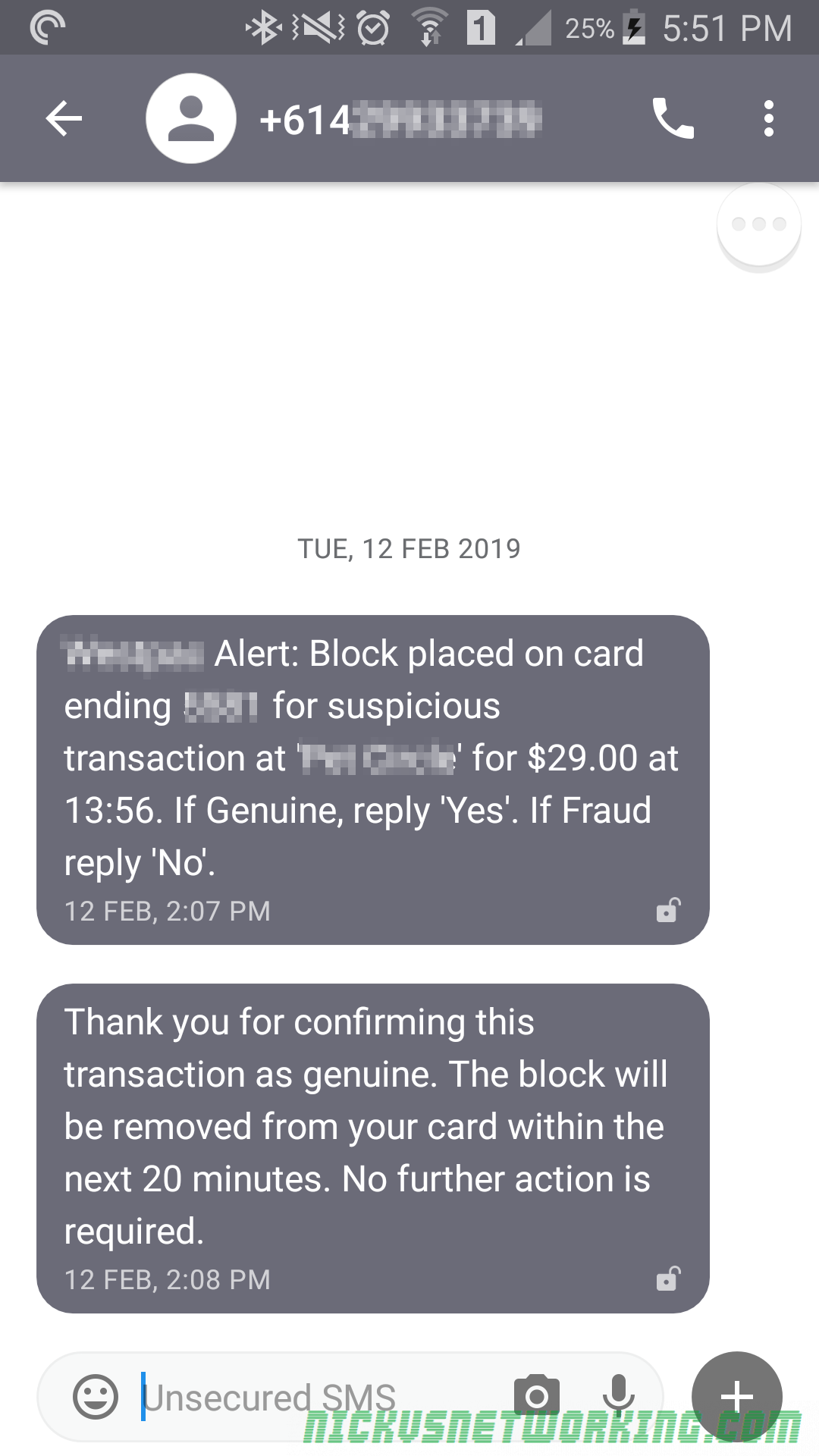
The other day I got an SMS from my bank, one of the big 4 Australian Banks.
BANKNAME Alert: Block placed on card ending in XXXX, for suspicious transaction at ‘THING NICK PURCHASED ONLINE’ for $29.00 at 13:56. If genuine, reply ‘Yes’. If Fraud, reply ‘No’.
SMS from bank
They’d detected possible fraud on my card, and were asking me to confirm if it was me or not by texting back.
That is my correct card number, and as it happens I had made an online purchase that was what it was querying.
I was already at my computer, so out of curiosity, opened the SMS Gateway I use, and set the caller ID to be my mobile number (Because spoofing Caller ID is trivial) and replied to the number the bank sent me the SMS from.
My phone beeped again:
Thank you for confirming this transaction is genuine. The block will be removed from your card within the next 20 minutes. No further action is required.
SMS from Bank
So what’s the issue here?
The issue is if someone were to steal your card details, and know your mobile number, they could just keep texting the bank’s verification line the word “yes” from an SMS gateway spoofing your Caller ID, the bank won’t block it.
No system is foolproof, but it seems a bit short sighted by this bank.
Texting back a code would be a better solution, because it would allow you to verify the person texting received the original SMS, or cycling the caller IDs from a big pool would decrease the likelihood of this working
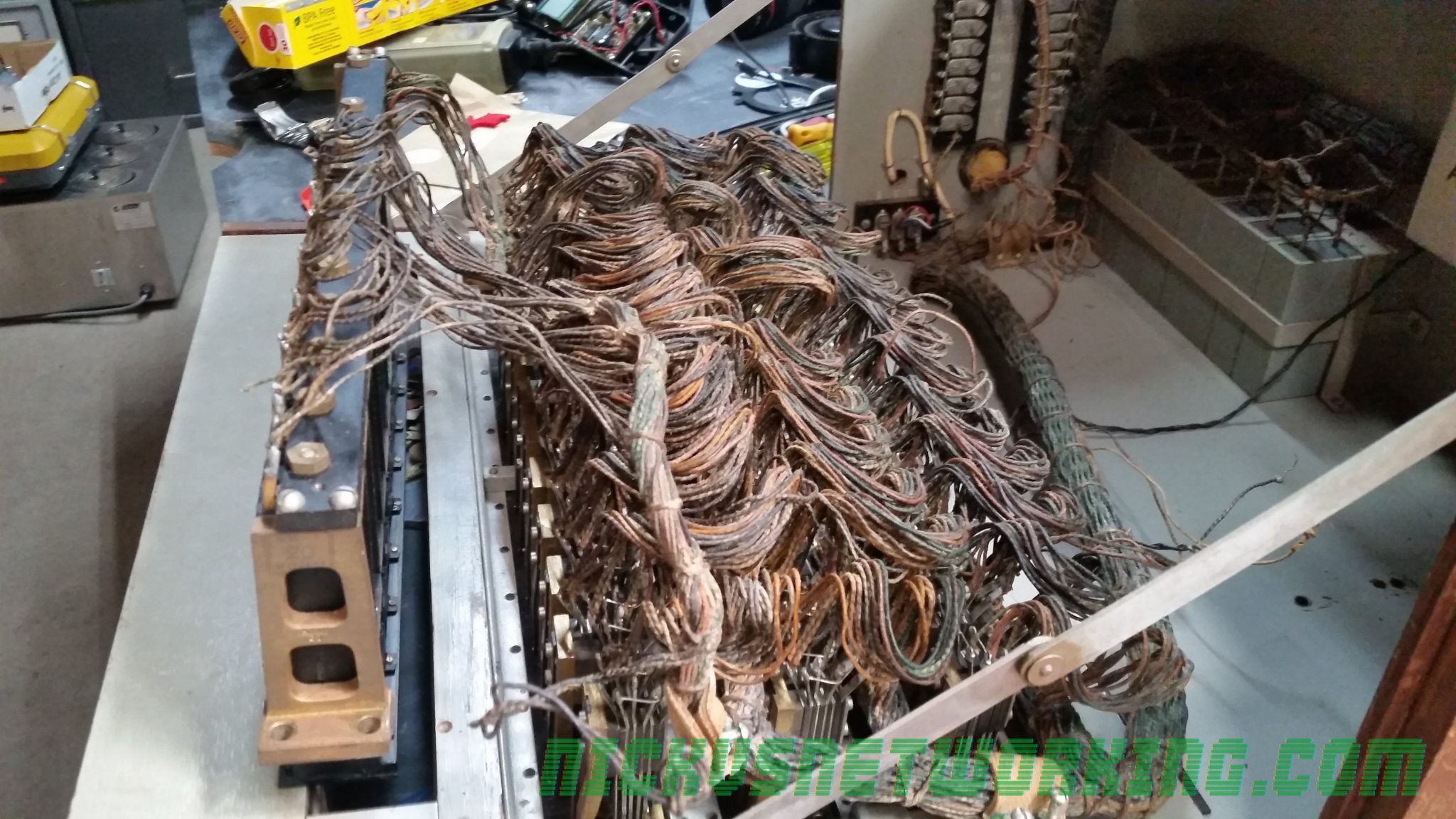
It’s no great secret I collect old phone stuff, I got this Melbourne made PMBX (Private Manual Branch Exchange) a while back, and I finally got around to doing something with it.
I’ve cleaned all the relays, got all the electronics happy (still need to replace the ring generator), taken everything out, sanded it, varnished it, 3D printed replacement knobs, cleaned the glass and got it looking all schmick.
Before
During
After
Glass replaced, contacts cleaned, wooden case taken apart, treated for boras, sanded and stained.
Next up fit all the 3D printed knobs, and repaint all the switch assemblies