In our last post we talked about getting our geospatial data right, and in our first post we covered the basics of adding sites and transmitters.
There’s a bit of a chicken-and-egg problem with site placement, antenna orientation, type and down-tilt.
If all our sites were populated and in place, we could look at optimizing coverage by changing azimuths / orientations, plug in our data and run some predictions / modeling and coming up with some solutions. Likewise if we’ve already done that we might want to calculate ideal down-tilt angles to get the most out of network.
But we’ve got no sites, no transmitters and no coverage predictions yet, so we’re probably going to need to ask ourselves a more basic, but harder question: Where will we put the cell sites?
To keep this easy we’ll focus on providing the South Western corner of the Island, a town called Tankerton, with only 3 cell sites.
Manual Site Selection
In the very first post we put up a few sites, we’ll do the same, let’s place 3 sites in the bottom right of the island and attempt to provide contiguous coverage for the town with them;
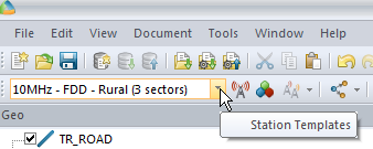
We’ll pick our Station Template and set it to FDD Rural as this is pretty remote.
Next we’ll add some sites and transmitters:
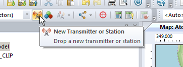
Click to place it on the map and add our cell sites;
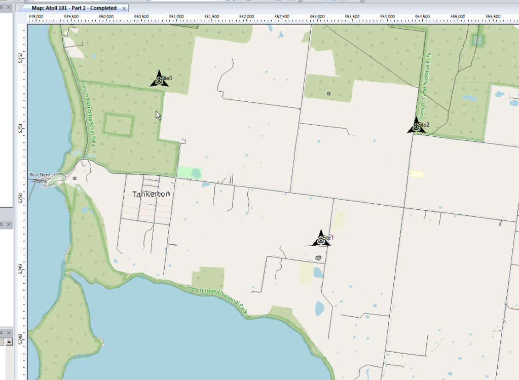
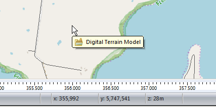
When we’re looking at where to place it, it’s good to remember that height (elevation) is good (To an extent), so when looking at where to place sites, keep an eye on the Z (Height) value in the bottom right, and try and pick sites with a good elevation.
Setting Computation Zone
As we’re only focusing on a small part of the island we’ll set a Computation Zone to limit the calculations / computations Atoll has to do to a set region.
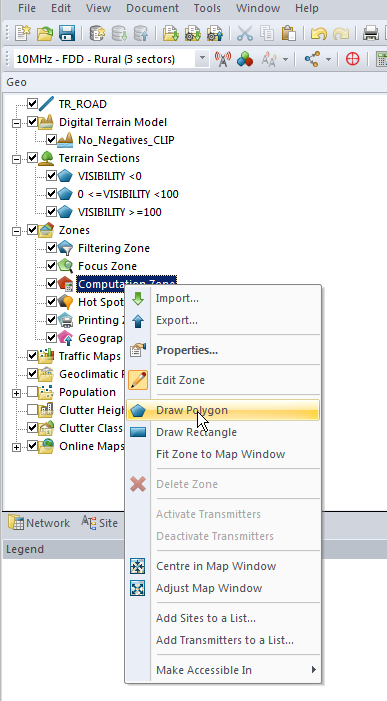
I’ve chosen to draw a Polygon around the area, but you could also just get away with drawing a Rectangle, around the area we’re interested in.
This just constrains everything so we’re only crunching numbers inside that area.
Predictions
So now we’ve put our 3 sites out & constrained to the Tankerton area, let’s see how much of the area we’ve covered, we’ll jump to the Network tab, right click on Predictions and select New Prediction
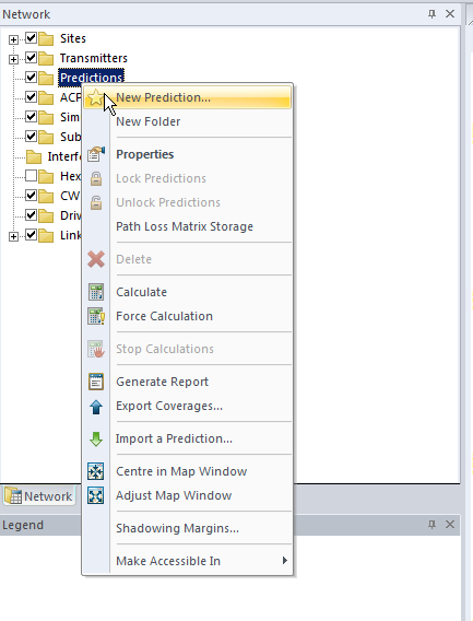
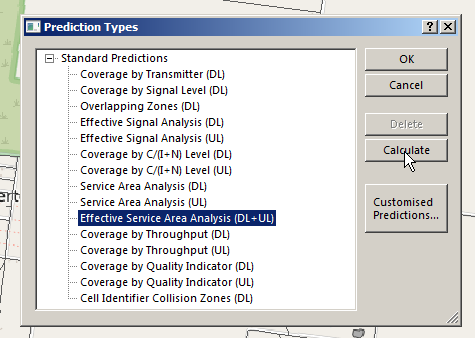
There’s a lot of predictions we can run, but we’ll go simple and select Effective Service Area Analysis (UL + DL) & click Calculate
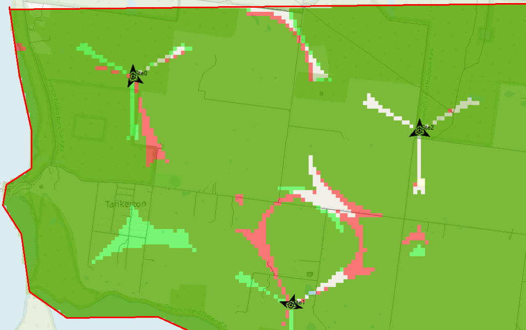
Atoll will crunch the numbers and give us a simple overlay, showing the areas with and without coverage.
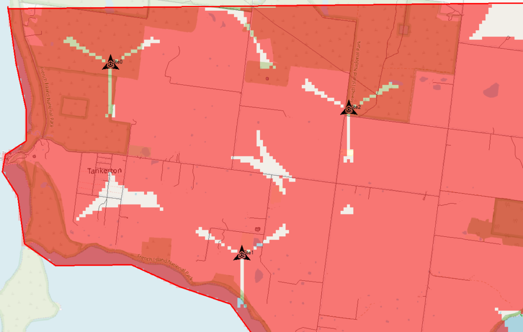
The areas in red are predicted to have coverage, and the areas with no shading will be our blackspots / “notspots”.
We’ve covered most of the area, but we can improve.
Manually Tweaking Attributes
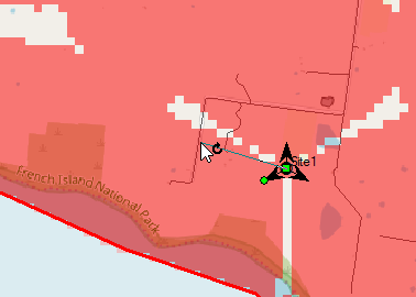
So there’s still some holes in our coverage, so let’s adjust the azimuth of some of the antennas and see if we can fill them.
Click on each of the arrows on the site, each of these represents an antenna / cell and we can change the angles.
So after a bit of fiddling I think I’ve got a better antenna azimuth for each of the sectors on each of my 3 sites.
Let’s compare that to what we had before to see if we’ve made it better or worse,
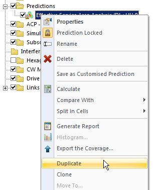
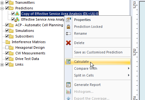
We’ll Duplicate the Effective Service Area Analysis prediction we created before & calculate it.
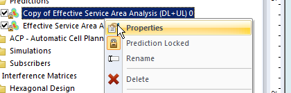
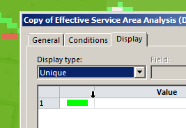
To make viewing a bit easier we’ll edit the properties of the copy and set it to a different colour:
Now I can see at a glance how much better we’re looking;
The obvious problem here is I could tweak and tweak and improve some things, make others worse, and we’d be here forever.
Luckily Atoll can do a better job of fiddling with each parameter for us and selecting the configuration that leads to the best performance in our RAN.
Automatic Cell Planning
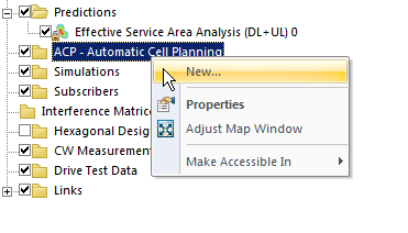
Enter Automatic Cell Planning, to adjust the parameters we set to find the most optimal setup,
We’ll right click on ACP – Automatic Cell Planning and create a new one.
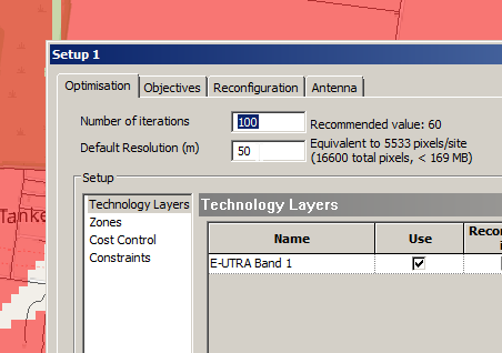
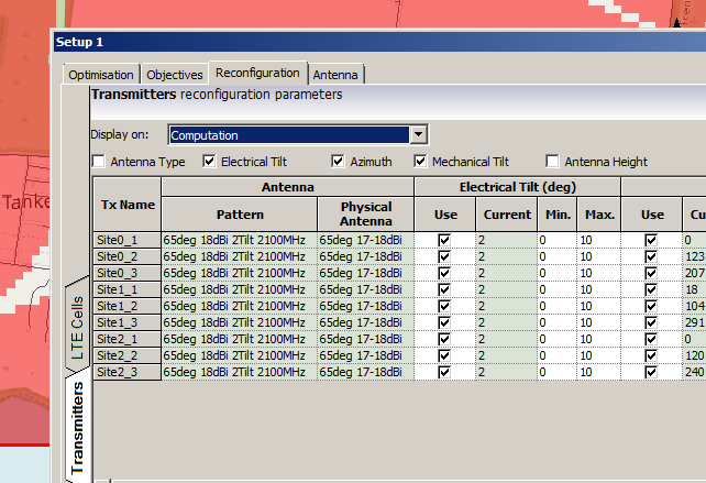
From here we set how many iterations we want to try out (more leads to better results but takes longer to compute), the parameters we want to change (ie Azimuth, Tilt, Antenna type, etc).
When you’ve set the parameters you want, click Run and Atoll will start running through possible parameter combinations and measuring how they perform.
Once it’s run you’ll be able to view the Optomization
The report shows you the results, improvements in RSSI and RSSQ;
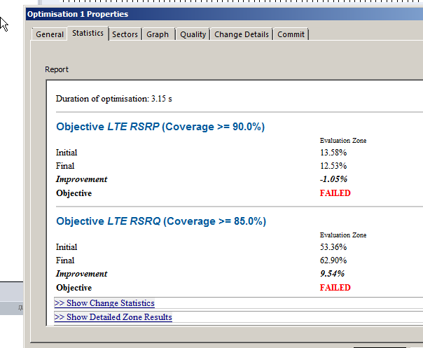
Here we can see we boosted the RSRQ (The quality of the signal) by 9.5%, but had to sacrifice RSRP (Signal power) by 1%.
Sacrificies have to be made, and if you’re happy with this you can view the details of the changes, and commit the adjustments.
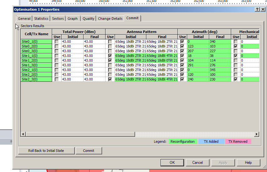
Committing the changes adjusts all the Transmitters in the area to the listed values, after which we can run our Predictions again to compare like we did earlier.
So that’s what we’ve got when we randomly place sites, we can use Atoll to optomize what we’ve already got, but what if we left the picking of cell sites up to Atoll to look for better options?
In our next post we’ll look at Site Selection using ACP, and constraining it. This means we can tell Atoll to just find the best sites, or load in a list of possible sites and let Atoll determine which are the best candidates.