We’ve covered a fair bit on authentication in 3GPP networks, SIM cards, HSS / AuC, etc, but never actually looked at the Confidentiality Algorithms in use,

While we’ve already covered the inputs required by the authentication elements of the core network (The HSS in LTE/4G, the AuC in UMTS/3G and the AUSF in 5G) to generate an output, it’s worth noting that the Confidentiality Algorithms used in the process determines the output.
This means the Authentication Vector (Also known as an F1 and F1*) generated for a subscriber using Milenage Confidentiality Algorithms will generate a different output to that of Confidentiality Algorithms XOR or Comp128.
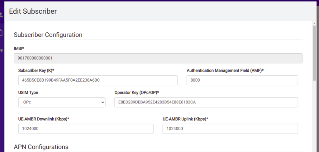
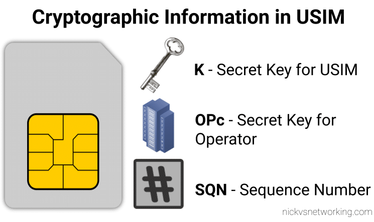
To put it another way – given the same input of K key, OPc Key (or OP key), SQN & RAND (Random) a run with Milenage (F1 and F1* algorithm) would yield totally different result (AUTN & XRES) to the same inputs run with a simple XOR.
Technically, as operators control the network element that generates the challenges, and the USIM that responds to them, it is an option for an operator to implement their own Confidentiality Algorithms (Beyond just Milenage or XOR) so long as it produced the same number of outputs. But rolling your own cryptographic anything is almost always a terrible idea.
So what are the differences between the Confidentiality Algorithms and which one to use?
Spoiler alert, the answer is Milenage.
Milenage
Milenage is based on AES (Originally called Rijndael) and is (compared to a lot of other crypto implimentations) fairly easy to understand,
AES is very well studied and understood and unlike Comp128 variants, is open for anyone to study/analyse/break, although AES is not without shortcomings, it’s problems are at this stage, fairly well understood and mitigated.
There are a few clean open source examples of Milenage implementations, such as this C example from FreeBSD.
XOR
It took me a while to find the specifications for the XOR algorithm – it turns out XOR is available as an alternate to Milenage available on some SIM cards for testing only, and the mechanism for XOR Confidentiality Algorithm is only employed in testing scenarios, not designed for production.
Instead of using AES under the hood like Milenage, it’s just plan old XOR of the keys.
Osmocom have an implementation of this in their CN code, you can find here.
Defined under 3GPP TS 34.108 8.1.2.1
Comp128
Comp128 was originally a closed source algorithm, with the maths behind it not publicly available to scrutinise. It is used in GSM A3 and A5 functions, akin to the F1 and F1* in later releases.
Due to its secretive nature it wasn’t able to be studied or analysed prior to deployment, with the idea that if you never said how your crypto worked no one would be able to break it. Spoiler alert; public weaknesses became exposed as far back as 1998, which led to Toll Fraud, SIM cloning and eventually the development of two additional variants, with the original Comp128 renamed Comp128-1, and Comp128-2 (stronger algorithm than the original addressing a few of its flaws) and Comp128-3 (Same as Comp128-2 but with a 64 bit long key generated).
Into the Future & 5G later releases
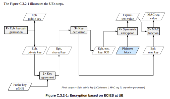
As options beyond just USIM authentication become available for authentication in 5G SA networks, additional algorithms can be used beyond EAP and AKA, but at the time of writing only TLS has been added. 5G adds SUCI and SUPI which provide a mechanism to keep the private identifier (IMSI) away from prying eyes (or antenna), which I’ve detailed in this post.