These are my lecture notes from IMT’s NET02x (4G Network Essentials) course, I thought I’d post them here as they may be useful to someone. You can find my complete notes here.
As spectrum is sparse and expensive, so it must be used wisely and shared across multiple users.
LTE shares spectrum in both frequency and time.
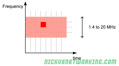
LTE can use bandwidths from 1.4Mhz to 20Mhz, based on the spectrum owned and needs of the area.
Spectrum is divided into sub-carriers, allowing each subcarrier to be allocated to a different user, and these subcarriers are re-allocated by the eNB based on the terminal’s needs.
Resource Element (RE)
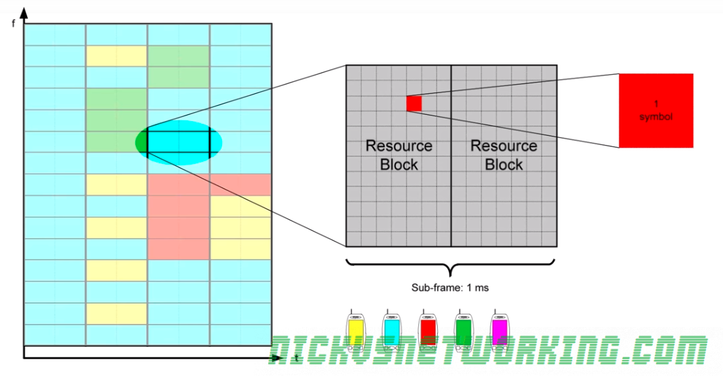
A Resource Element is the time and frequency a single symbol can be transmitted on.
Resource Elements are allocated by the eNB to UEs and the UE transmits on it’s allocated resource element one symbol.
The size of the data in the symbol is defined by the MCS used.
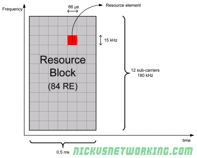
One Resource Element is contained within 1 subcarrier of 15kHz lasting 66μ s.
Resource Blocks (RB)
Because resource elements are so small, they’re managed in Resource Blocks.
Each Resource Block lasts 0.5ms with 12 sub carriers on each, allowing for 84 Resource Elements in per Resource Block.
The number of Resource Blocks that can be used is determined by the spectrum available.
As we can calculate a Resource Block occupies 180kHz of bandwidth, how many Resource Blocks we can have is determined by how many will fit into our bandwidth.
A system using the minimum bandwidth of 1.4Mhz will have 6 RBs available (1.4Mhz divides into 6 complete 180kHz RBs), while one using the maximum of 20Mhz will have 100 RBs available.
Not all the REs in an RB can be used by terminals though, many of them are reserved for LTE control channels.

Meaning only the white REs shown above can be filled with user traffic.
Sub-Frame
Every 1ms (or 2 Resource Blocks) LTE reallocates the RBs to the terminals that need to communicate.
This means Resource Blocks are allocated in pairs, called a subframe, lasting 1ms.
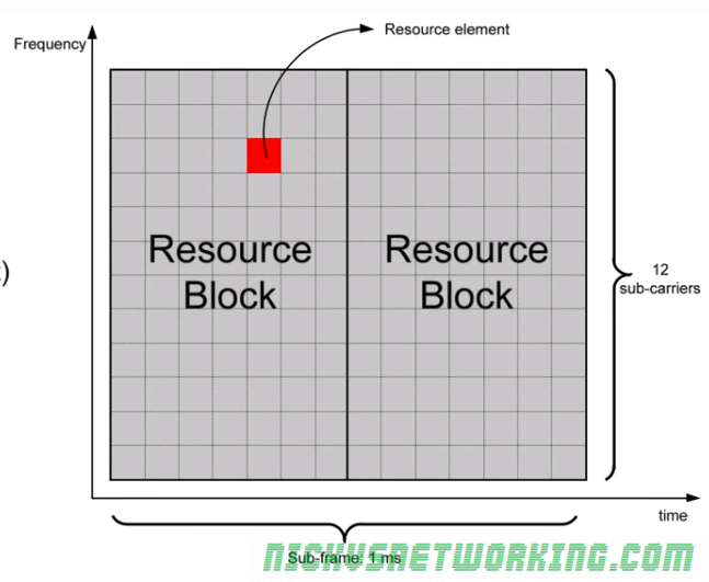
Subframe, RB, RE Hierarchy
Each subframe is 1ms long and made up of 2 0.5ms Resource Blocks.
Each Resource Block contains 84 Resource Elements, each of which contain one symbol of data.
Resource Allocation in Uplink
When a device needs to transmit data it is allocated one or more resource blocks.
If the number of resource blocks is not enough it can be allocated more in the next subframes.
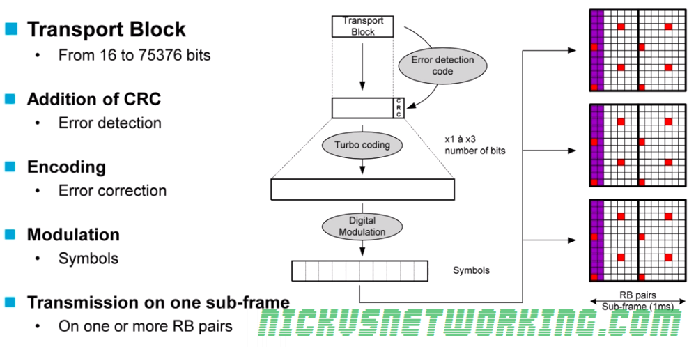
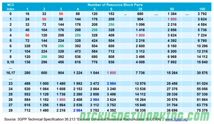
The amount of data a device can transmit in each subframe is called a Transport Block and is made up of the number of RBs and the modulation (MCS) used.
The sub frame containing contain data for various terminals is shown below in different colors.
Transmission Chain
Transport Blocks are filled with data based on the Transport Block size.
CRC is added to detect errors.
Data is encoded to help recover data containing errors. (Defined by MCS)
Data is modulated (Using modulation scheme defined by MCS)
Data is transmitted in the user-data part that has been allocated in one or more Resource Block Pairs.
