Note: All information contained here is sourced from: Photos provided by NBNco’s press pages, Googling part numbers from these photos, and public costing information.
This post covers the specifics and capabilities of NBNco’s FTTN solution, and is the result of some internet sleuthing.
If some of the info in here is now out of date, I’d love to know, let me know in the comments or drop me an email and I’ll update it.
FTTN in Numbers
A total of 24,544 nodes have been deployed upon completion of roll out. Each node is provisioned with 384 subscriber ports.
The hardware has 10Gbps shared between the 384 subscriber lines, equating to 208Mbps per subscriber.
Construction costs were $2.311 billion and hardware costs were $1.513 billion,
For the hardware this equates to $61,644 per node or $160 per subscriber line connected (each node is provisioned with 384 ports)
Full cost for node including hardware, construction and provisioning is $244,150 per node, which is $635 per port.
To operate the FTTN infrastructure costs $709 million per year (Made up of costs such as power, equipment servicing and spares). This equates to $28k per node per annum, or $75 per subscriber. (This does not take into account other costs such as access to the copper, transmission network, etc, just the costs to have the unit powered on the footpath.)
Overview
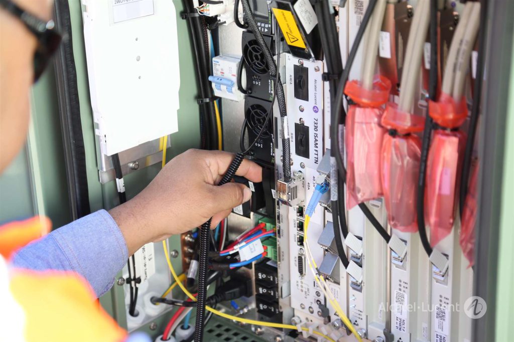
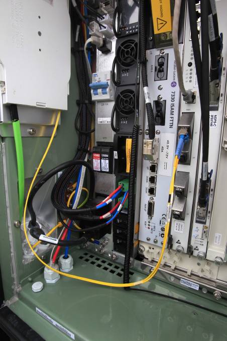
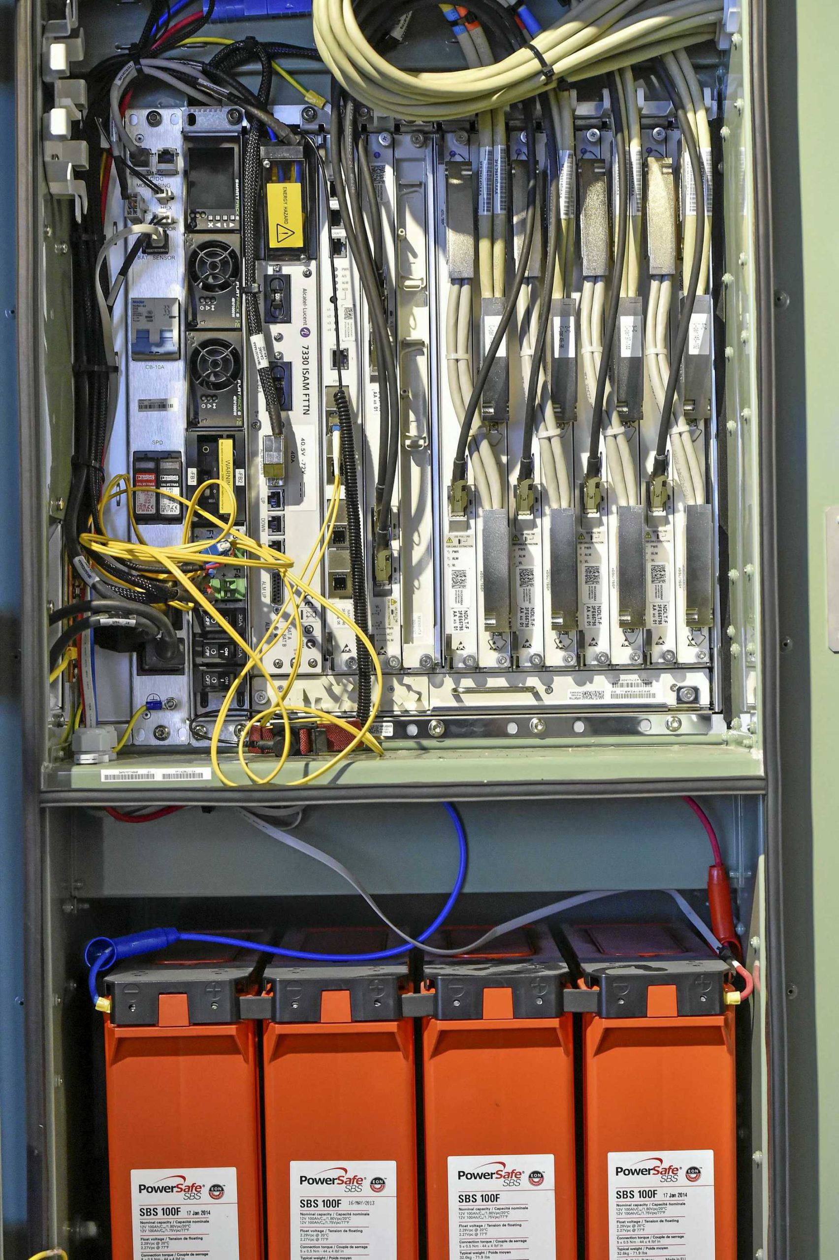
Inside the FTTN cabinets is a Alcatel Lucent (now Nokia) ISAM 7330 cabinet mounted on it’s side,
On the inside left of the door is a optic fibre tray where the transmission links come into the cabinet,
On the extreme left is a custom panel. It contains I/Os that are fed to the 7330, such as door open sensor, battery monitoring, AC power in, SPD and breaker.
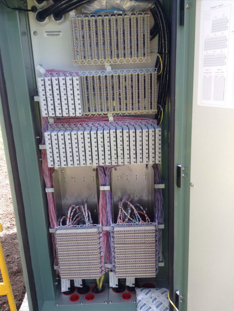
Connection to subscriber lines happens on a frame at the end of the cabinet.
Alcatel Lucent ISAM 7330 FTTN
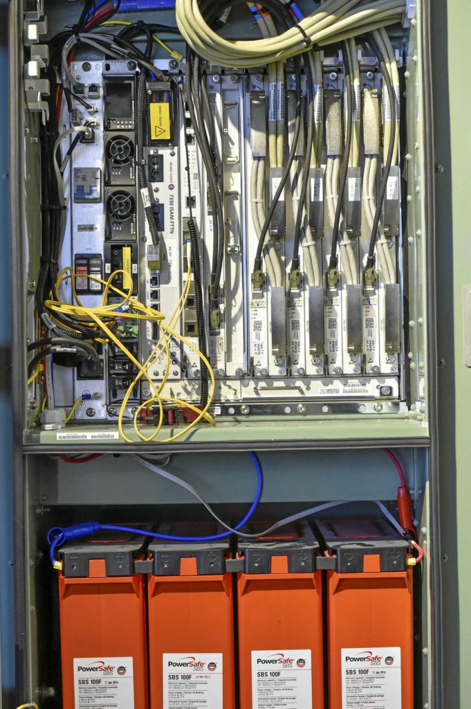
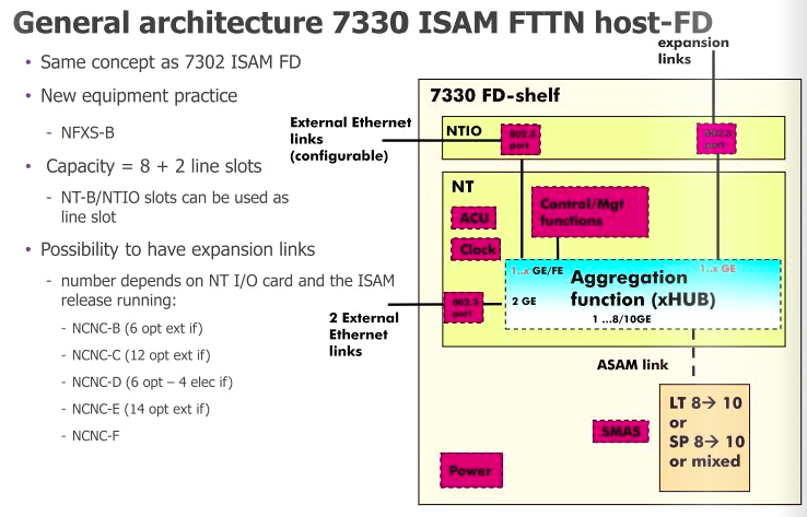
NBN co’s nodes are made up of Alcatel Lucent (Now Nokia) ISAM (Intelligent Services Access Manager) 7330 FTTN rack mounted it’s side.
| Slot | Type | Function |
| 1 | GFC (General Facilities Card) | Power and alarm management |
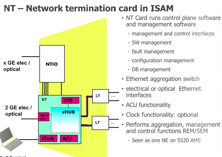
| 2 | NT Slot (NANT-E Card) | Main processing and transmission |
| 3 | NTIO Slot (NDPS-C Card) | VDSL vectoring number-crunching |
| 4 | NT Slot (Free) | Optional (Unused) backup Main processing and transmission |
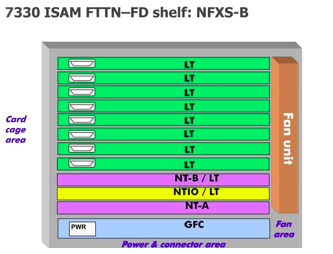
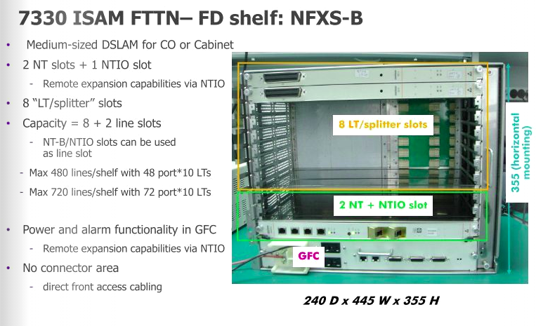
| 5-12 | LT (NDLT-F) | 48 Port VDSL Subscriber DSLAM Interfaces |
First up is the GFC (General Facilities Card) which handles alarm input / output, and power distribution. This connects to the custom IO panel on the far left of the cabinet, meaning the on-board IO ports aren’t all populated as it’s handled by the IO panel. (More on that later)
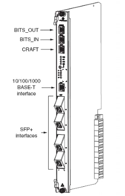
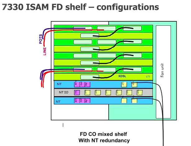
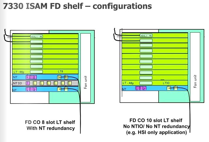
Next up is the first NT slot, there are two on the 7330, but in NBN’s case, only one is used; the second can be used for redundancy if one of the cards were to fail, but it seems this option has not been selected. In the first and only populated NT slot is an NANT-E Card (Combined NT Unit E) which handles transmission and main processing.
All the ISAM NANT cards support support RIPv2! But only the NANT-E card also supports BGP – Interestingly they don’t have BGP on all the NANT cards?
To the right of that is the NTIO slot, which has a NDPS-C card, which handles the vector processing for VDSL.
Brief overview of Vectoring: By adding vectoring to DSL signals allows noise on subscriber loops to be modeled, and then cancelled out with an integrated anti-phase signal matching that of the noise.
The vectoring in VDSL relies on pretty complex number crunching as the DSLAM has to constantly process the vectoring coefficients which are different for each line and can change based on the conditions of the subscriber loop etc. To do this the NDPS-C has two roles;
The NDPS-C’s Vectoring Control Entity performs non-real time calculations of vectoring coefficients and handles joining and leaving of vectored VDSL2 lines.
While the NDPS-C’s Vectoring Processor performs the real time matrix calculations based on crosstalk correction samples for the VDSL symbols collected from the subscriber lines.
The NDPS-C has a Twinax connection to every second LT Card.
After the NTIO slot is the unused NT slot.
Finally we have the 8 LT slots for line cards, which for FTTN is using the NDLT-F are 48 port line cards.
The 8 card slots allows 384 subscriber lines per node.
These are the cards which the actual subscriber lines ultimately connect to. With 10Gbps available from the NT to the LTs, means each LT card with 48 subs so 208 Mbps per subscriber max theoretical throughput.
POTS overlay is supported, this allowed VF services coexisted on the same copper during the rollout. M / X pairs are no longer added inline on new connections. (More on that on cabling).
Power & Environment
The 7330 has a 40 amp draw at -48v would mean the unit consumes 1920w
The -48v supply is provided by 2x Eltek Flatpack2 rectifiers, each providing 1Kw each.
These can be configured to provide 1Kw with redundancy to protect against the failure of one of the Flatpack2 units, or 2Kw with no redundancy, which is what is used here.
On the extreme left is a custom panel. It contains alarm I/Os that are fed to the 7330, such as door open sensor, battery monitoring, etc.
It also is the input for AC power in, surge protection device and breakers.
I did have some additional information on the batteries used and the power calculations, however NBNco’s security team have asked that this be removed.
Cabling
Incoming transmission fiber comes in on NBNco’s green ribbon fibre, which terminates on a break out tray on the left hand side wall of the cabinet. Spliced inside the tray is a duplex LC pigtail for connecting the SMF to the 7330. I don’t have the specifics on the optics used.
Subscriber lines come in via an IDC distribution frame (Quante IDS) on the right hand side end of the cabinet, accessed through a seperate door.
This frame is referred to as the CCF – Cross Connect Frame.
There are two sets of blocks on the CCF, termination of ‘X’ and ‘C’ Pairs.
‘X’ Pairs are the VF Pairs (PSTN lines) connecting to the pillar where they are jumpered back to the ‘M’ pairs back to the serving exchange,
‘C’ Pairs are the pairs containing combined VDSL & VF services to to the pillar where they are jumpered to the ‘O’ pairs which run out to the customer’s premises,
