Tag Archives: RNTI

IMTx: NET02x (4G Network Essentials) – Mobility Management – 1. Managing Location

These are my lecture notes from IMT’s NET02x (4G Network Essentials) course, I thought I’d post them here as they may be useful to someone. You can find my complete notes here.

As we saw with the Network Triggered Service Request, the network needs to know which eNB / cell the UE is currently being served by.

The UE knows which cell it should use as it’s always listening on the broadcast channel to know the received power levels of the nearby eNBs.

Paging

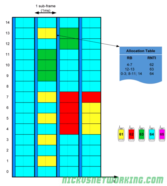
If our UE is in ECM IDLE state and the network needs to contact the UE, the eNB sends sends a Paging Request on the Beacon (Broadcast) Channel with the UE’s RNTI.

The UE is always listening on the Beacon Channel for it’s own RNTI, and when it hears it’s own RNTI it follows the process to come back from ECM_IDLE state to ECM_CONNECTED state.

For this to work the network needs to know which eNB to send the Paging request to.

For this to work our UE would need to inform the network each time it changes eNB, but, as we’ve touched upon several times, minimizing power consumption is a constant architecture constraint in LTE.

So if the UE has to transmit each time a UE moves to a different eNB / Cell, the UE power consumption would be high and the battery life of the UE would be low.

If we imagine driving along a freeway at speed, with each eNB serving an area of 1km, at 60kph, our UE would change cells every minute, and if the UE needs to transmit to let the network know it’s changing location, we’d be transmitting data every 60 seconds even if the UE is sitting in our pocket, all these transmissions would lead to lower battery life on the UE.

Tracking Areas

To work around the power wastage of each UE transmitting data to the network to let it know each time it changes eNB, 3GPP designers decided to group eNBs in the same geographic area into Tracking Areas or TAs.

This means instead of the network knowing exactly which eNB a UE is located in, it has it’s location down to a tracking area made up of several eNBs. (Tens to hundreds of cells per TA)

To go back to our freeway example, we might group all the eNBs along a freeway into one Tracking Area, all of which broadcast the ID of each eNB and the Tracking Area of each eNB.

As the UE moves from one eNB to another eNB in the same Tracking Area, there’s no need for the UE to send a Tracking Area Update message as it’s reamining in the same Tracking Area.

Tracking Area Update messages only need to be sent when the UE moves to an eNB in a different Tracking Area.

UEs can move from cell to cell inside TA1 without needing to update the network.
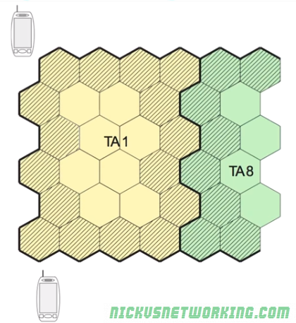
Only when a UE moves from a eNB / cell in TA1 to TA2, does it need to send a Tracking Area Update message to the network.

Paging a Tracking Area

As the network knows the location of our UE down to a tracking area, when it comes time to Page a UE a Paging Request is simply sent from the MME to all eNBs in the Tracking Area that the UE is in.

This means the RNTI of the UE is broadcast out of all eNBs in that tracking Area, and the UE establishes connectivity once again with it’s nearest eNB.

IMTx: NET02x (4G Network Essentials) – Radio Interface – 3. Packet Allocation

These are my lecture notes from IMT’s NET02x (4G Network Essentials) course, I thought I’d post them here as they may be useful to someone. You can find my complete notes here.

Allocation Tables

To inform UEs of which resources are allocated to it, the eNB regularly publishes Allocation Tables with this information.

Resources are allocated dynamically, by the eNB to all the UEs it is serving.

Because the eNB manages all the resources, the eNB must inform the UEs which resources are allocated to which UEs.

This is broken into two functions:

  • A UE must be able to be informed it’s going to receive data (downlink) and be allocated the resources for it.
  • A UE must be able to request resources from the eNB to send data (uplink) and be allocated resources for it.

The eNB manages all resource allocation, for downlink and uplink, when they are needed. This is done through an allocation table published by the eNB every subframe (1ms).

There are two allocation tables – One for uplink, one for downlink.

Addressing on the Radio Interface – RNTI

As an allocation table needs to allocate resources to each UE it needs a way to address them.

GUTI, IMSI, TMSI etc, are all too long (allocation tables are published every subframe so need to be a small as possible).

Instead for addressing in the allocation tables as RNTI – Radio Network Temporary Identifier is issued by the eNB to each UE it is serving, the RNTI is issued by the eNB and only valid for that cell, if the user moves to another cell served by another eNB another RNTI is allocated by that eNB.

The RNTI is 16 bits long, meaning it can store 65,536 decimal values. (65,536 UEs)

Allocation on Downlink

Resource allocation for the downlink is managed by the eNB, which publishes allocation tables every subframe defining which resource blocks are allocated to which UE.

The resource blocks contains the RNTI of each UE to receive data and the resource blocks it’s data will be contained in.

Each UE listens for the allocation tables published in each subframe, and if the UE sees it’s own RNTI in the allocation table it listens on the resource blocks allocated to it.

In the example above we can see the allocation table in the dark blue colour, published every 1ms (aka every subframe).

In this example the UE that has been assigned RNTI 63 (represented in green) has got resource blocks 12 & 13 assigned to it, so will listen on 12 and 13 to get it’s downlink data.

Because UEs only listen for the allocation tables and the resource blocks assigned to them, it leads to power savings on the UE as they don’t all need to listen / decode to all resource blocks. Power savings on the UE translate to better battery efficiency.

The UE with RNTI 61 for example, does not get allocated any resource blocks in the downlink in the example allocation table, so it listens for the allocation table and then goes into standby mode until the next allocation table is published.

The allocation tables are contained in the Physical Downlink Control Channel (PDCCH) a channel used only by the eNB to broadcast resource allocation tables and control data.

The actual downlink data for each UE is contained in the Physical Downlink Shared Channel (PDSCH)

Allocation in the Uplink

Allocation in the uplink is similar to allocation in the downlink, however there are some important differences.

  • The UE must request the resources from the eNB and wait for them to be allocated in the next uplink resource block.
  • There is a 4ms delay between a resource block being allocated in an allocation table by the eNB for the uplink and it being used by the UE to send data. This gives the UE time to get the data ready to go into the resource block.

The UE requests a resource from the eNB (covered later) and the eNB publishes an allocation table in the next subframe, however this allocation table is to be used in 4 subframes time.

The UE then buffers this allocation table and uses it in 4 subframes time.

By having this delay in using the resource table / allocating resource tables in advance, it allows our UEs to prepare the message for transmission, encode it, modulate it, etc.

The image below shows the UE in red requesting a resource for uplink from the eNB, the eNB then publishes the allocation table for 4 subframes time, the UE waits for 4 subframes to pass and then the UE transmits using the resources allocated in the allocation table published 4ms prior.

For example in the image below the UE with the RTNI of 64, represented in light blue, has requested a resource to send data (uplink), the eNB publishes an uplink allocation table in the next subframe, and the UE has then 4 subframes to prepare the data for transmission before sending the data using the resources allocated in the allocation table sent to it 4 subframes prior.

Like in the Downlink, Uplink transmissions are managed by a Control Channel and data is contained within a Data Channel.

The Physical Uplink Control Channel (PUCCH) contains the control information and the resource tables for the uplink (to be used in 4 subsframes time), shown in gray.

The data being sent from the UEs is contained in Physical Uplink Shared Channels (PUSCH) allocated 4ms prior in a PUCCH.

When a UE has data to transmit it transmits on the PUCCH to request a resource block for the uplink data.