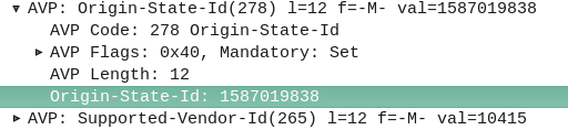
The Origin-State-Id AVP solves a kind of tricky problem – how do you know if a Diameter peer has restarted?
It seems like a simple problem until you think about it. One possible solution would be to add an AVP for “Recently Rebooted”, to be added on the first command queried of it from an endpoint, but what if there are multiple devices connecting to a Diameter endpoint?
The Origin-State AVP is a strikingly simple way to solve this problem. It’s a constantly incrementing counter that resets if the Diameter peer restarts.
If a client receives a Answer/Response where the Origin-State AVP is set to 10, and then the next request it’s set to 11, then the one after that is set to 12, 13, 14, etc, and then a request has the Origin-State AVP set to 5, the client can tell when it’s restarted by the fact 5 is lower than 14, the one before it.
It’s a constantly incrementing counter, that allows Diameter peers to detect if the endpoint has restarted.
Simple but effective.
You can find more about this in RFC3588 – the Diameter Base Protocol.
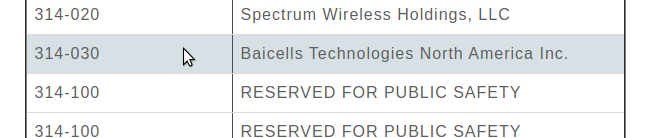
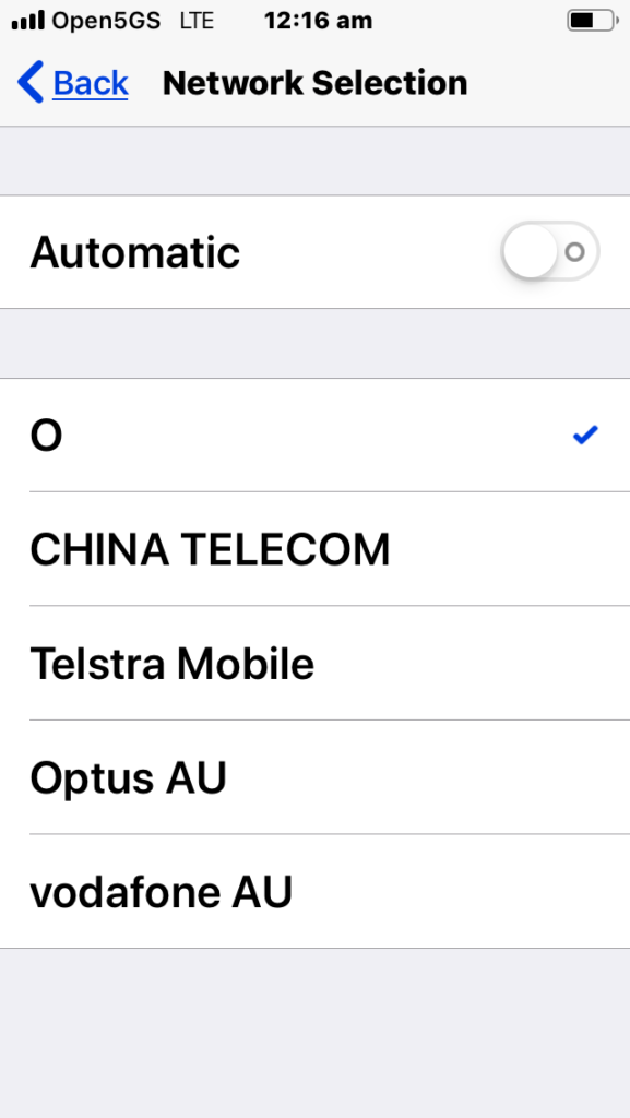
If you’re using BaiCells hardware you may have noticed the new eNBs and USIMs are shipping with the PLMN of MCC 314 / MNC 030.
First thing I do is change the PLMN, but I was curious as to why the change.
It seems 314 / 030 was never assigned to BaiCells to use and when someone picked this up they were forced to change it.
The MCC (Mobile Country Code) part is dictated by the country / geographic area the subscribers’ are in, as defined by ITU, whereas the MNC (Mobile Network Code) allocation is managed by the regional authority and ITU are informed as to what the allocations are and publish in their bulletins.
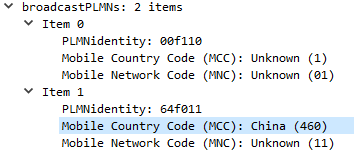
Well, SIM cards will have a different IMSI / PLMN, but the hardware supports Multi-Operator Core Network which allows one eNB to broadcast multiple PLMNs, so if you update your eNB it can broadcast both!
There’s a lot of layers of signalling in the LTE / EUTRAN attach procedure, but let’s take a look at the UE attach procedure from the Network Perspective.
We won’t touch on the air interface / Uu side of things, just the EPC side of the signaling.
To make life a bit easier I’ve put different signalling messages in different coloured headings:
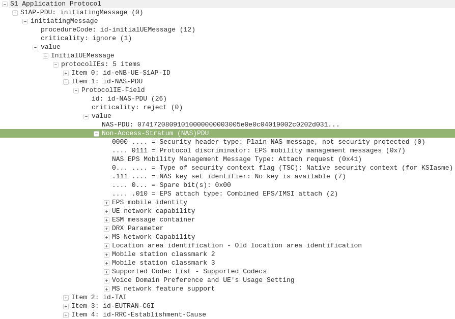
After a UE establishes a connection with a cell, the first step involved in the attach process is for the UE / subscriber to identify themselves and the network to authenticate them.
The TAI, EUTRAN-CGI and GUMME-ID sections all contain information about the serving network, such the tracking area code, cell global identifier and global MME ID to make up the GUTI.
The NAS part of this request contains key information about our UE and it’s capabilities, most importantly it includes the IMSI or TMSI of the subscriber, but also includes important information such as SRVCC support, different bands and RAN technologies it supports, codecs, but most importantly, the identity of the subscriber.
If this is a new subscriber to the network, the IMSI is sent as the subscriber identity, however wherever possible sending the IMSI is avoided, so if the subscriber has connected to the network recently, the M-TMSI is used instead of the IMSI, and the MME has a record of which M-TMSI to IMSI mapping it’s allocated.
Diameter: Authentication Information Request
MME to HSS
The MME does not have a subscriber database or information on the Crypto side of things, instead this functionality is offloaded to the HSS.
I’ve gone on and on about LTE UE/Subscriber authentication, so I won’t go into the details as to how this mechanism works, but the MME will send a Authentication-Information Request via Diameter to the HSS with the Username set to the Subscriber’s IMSI.
Diameter: Authentication Information Response
HSS to MME
Assuming the subscriber exists in the HSS, a Authentication-Information Answer will be sent back from the HSS via Diameter to the MME, containing the authentication vectors to send to the UE / subscriber.
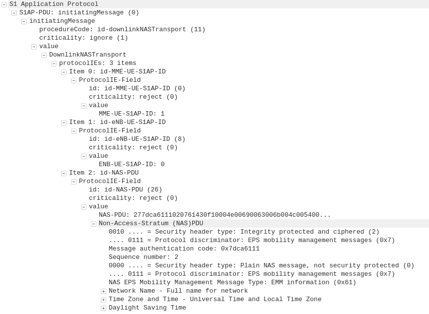
Now the MME has the Authentication vectors for that UE / Subscriber it sends back a DownlinkNASTransport, Authentication response, with the NAS section populated with the RAND and AUTN values generated by the HSS in the Authentication-Information Answer.
The Subscriber / UE’s USIM looks at the AUTN value and RAND to authenticate the network, and then calculates it’s response (RES) from the RAND value to provide a RES to send back to the network.
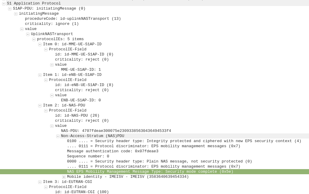
S1AP: UplinkNASTransport, Authentication response
eNB to MME
The subscriber authenticates the network based on the sent values, and if the USIM is happy that the network identity has been verified, it generates a RES (response) value which is sent in the UplinkNASTransport, Authentication response.
The MME compares the RES sent Subscriber / UE’s USIM against the one sent by the MME in the Authentication-Information Answer (the XRES – Expected RES).
If the two match then the subscriber is authenticated.
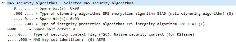
The DownlinkNASTransport, Security mode command is then sent by the MME to the UE to activate the ciphering and integrity protection required by the network, as set in the NAS Security Algorithms section;
The MME and the UE/Subscriber are able to derive the Ciphering Key (CK) and Integrity Key (IK) from the sent crypto variables earlier, and now both know them.
S1AP: UplinkNASTransport, Security mode complete
eNB to MME
After the UE / Subscriber has derived the Ciphering Key (CK) and Integrity Key (IK) from the sent crypto variables earlier, it can put them into place as required by the NAS Security algorithms sent in the Security mode command request.
It indicates this is completed by sending the UplinkNASTransport, Security mode complete.
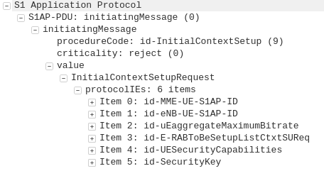
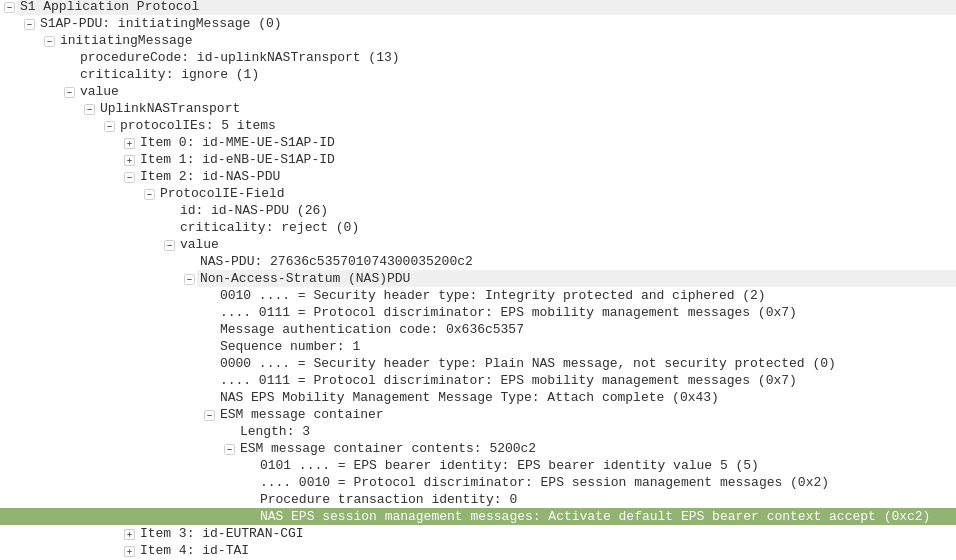
At this stage the authentication of the subscriber is done, and a default bearer must be established.
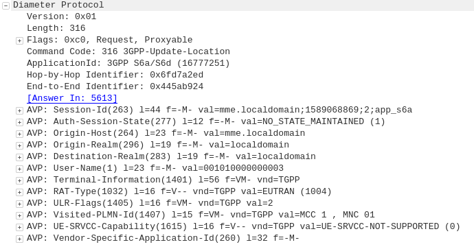
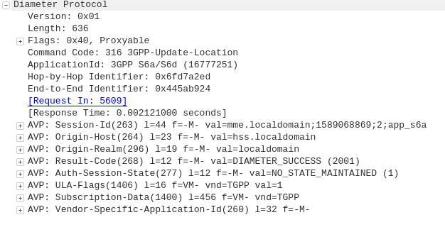
Diameter: Update Location Request
MME to HSS
Once the Security mode has been completed the MME signals to the HSS the Subscriber’s presence on the network and requests their Subscription-Data from the HSS.
Diameter: Update Location Answer
HSS to MME
The ULA response contains the Subscription Data used to define the data service provided to the subscriber, including the AMBR (Aggregate Maximum Bit Rate), list of valid APNs and TAU Timer.
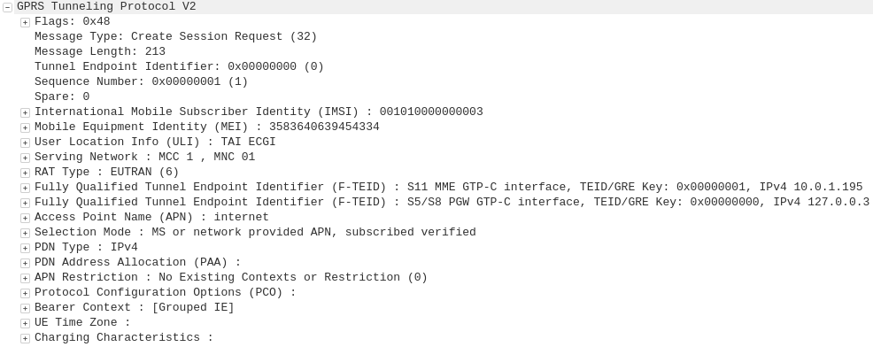
GTP-C: Create Session Request
MME to S-GW
The MME transfers the responsibility of setting up the data bearers to the S-GW in the form of the Create Session Request.
This includes the Tunnel Endpoint Identifier (TEID) to be assigned for this UE’s PDN.
The S-GW looks at the request and forwards it onto a P-GW for IP address assignment and access to the outside world.
GTP-C: Create Session Request
S-GW to P-GW
The S-GW sends a Create Session Request to the P-GW to setup a path to the outside world.
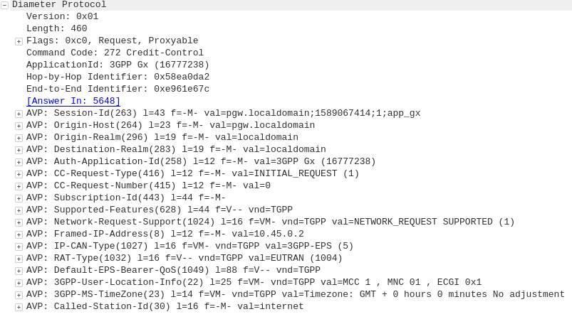
Diameter: Credit Control Request
P-GW to PCRF
To ensure the subscriber is in a state to establish a new PDN connection (not out of credit etc), a Credit Control Request is sent to the HSS.
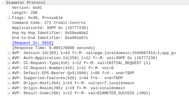
Diameter: Credit Control Answer
PCRF to P-GW
Assuming the Subscriber has adequate credit for this, a Credit Control Answer is sent and the P-GW and continue the PDN setup for the subscriber.
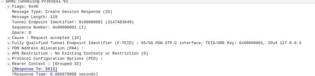
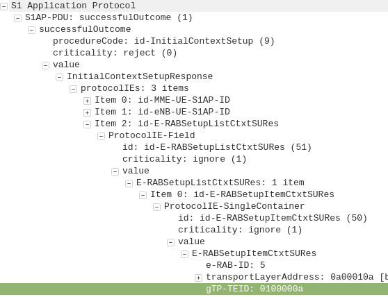
GTP-C: Create Session Response
P-GW to S-GW
The P-GW sends back a Create Session Response, containing the IP address allocated to this PDN (Framed-IP-Address).
GTP-C: Create Session Response
S-GW to MME
The S-GW slightly changes and then relays the Create Session Response back to the MME,
This message is sent to inform the eNB of the details of the PDN connection to be setup, ie AMBR, tracking area list, APN and Protocol Configuration Options,
This contains the Tunnel Endpoint Identifier (TEID) for this PDN to identify the GTP packets.
These posts focus on the use of Diameter and SIP in an IMS / VoLTE context, however these practices can be equally applied to other networks.
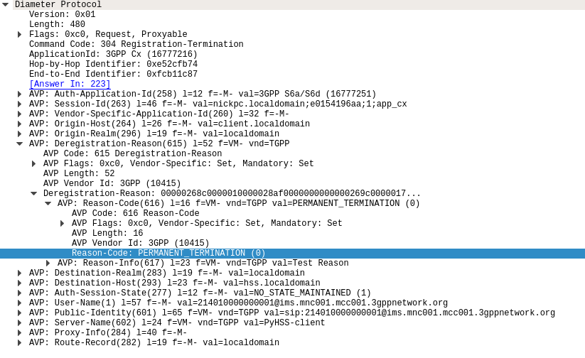
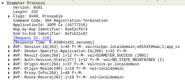
The Registration-Termination Request / Answer allow a Diameter Client (S-CSCF) to indicate to the HSS (Diameter Server) that it is no longer serving that user and the registration has been terminated.
Basics:
The RFC’s definition is actually pretty succinct as to the function of the Server-Assignment Request/Answer:
The Registration-Termination-Request is sent by a Diameter Multimedia server to a Diameter Multimedia client in order to request the de-registration of a user.
Reference: TS 29.229
The Registration-Termination-Request commands are sent by a S-CSCF to indicate to the Diameter server that it is no longer serving a specific subscriber, and therefore this subscriber is now unregistered.
There are a variety of reasons for this, such as PERMANENT_TERMINATION, NEW_SIP_SERVER_ASSIGNED and SIP_SERVER_CHANGE.
The Diameter Server (HSS) will typically send the Diameter Client (S-CSCF) a Registration-Termination-Answer in response to indicate it has updated it’s internal database and will no longer consider the user to be registered at that S-CSCF.
Packet Capture
I’ve included a packet capture of these Diameter Commands from my lab network which you can find below.
Note: I’m running version 19.12.0 which I installed from the repos due to issues with 20.4.0 (latest when I wrote this) and stability on LimeSDR.
I wrote the other day about installing SRS LTE stack,
But installing it is one thing, meeting all the requirements to use it with your SDR hardware turns out to be another whole thing all together.
srsENB is a software defined eNodeB, allowing you to use a Software Defined Radio to serve as an eNodeB, UE and a few other utilities.
SRS’ implementation of the eNB is supposed to be 3GPP R10 compliant and supports eMBMS to boot.
Meeting Dependencies
Installing prerequisites
I’m using a LimeSDR, but these instructions also for for the BladeRF. I found the frequency stability of my BladeRF X40 wasn’t great, meaning when running SRS’s eNodeB the cell wasn’t visible to my UE.
sudo apt install tree vim git g++ make cmake pkg-config python-numpy swig libi2c-dev libusb-1.0-0-dev libfftw3-dev libmbedtls-dev libboost-program-options-dev libconfig++-dev libsctp-dev gnuradio
Install SoapySDR from Source
git clone https://github.com/pothosware/SoapySDR.git
pushd SoapySDR
git checkout tags/soapy-sdr-0.7.2 -b soapy-sdr-0.7.2
mkdir build
cd build
cmake ..
make
sudo make install
sudo ldconfig
popd
Install LimeSuite
You can skip this if you’re using a BladeRF
git clone https://github.com/myriadrf/LimeSuite.git
pushd LimeSuite
#git checkout tags/v19.04.0 -b v19.04.0
mkdir builddir
cd builddir
cmake ..
make
sudo make install
sudo ldconfig
cd ../udev-rules
sudo sh ./install.sh
popd
Install BladeRF
You can skip this if using a LimeSDR
git clone https://github.com/Nuand/bladeRF.git
pushd bladeRF/host/
mkdir build
cd build/
cmake -DCMAKE_BUILD_TYPE=Release -DCMAKE_INSTALL_PREFIX=/usr/local -DINSTALL_UDEV_RULES=ON -DBLADERF_GROUP=plugdev ..
make
sudo make install
sudo ldconfig
sudo mkdir -p /etc/Nuand/bladeRF/
sudo wget https://www.nuand.com/fpga/hostedx40-latest.rbf --output-document /etc/Nuand/bladeRF/hostedx40.rbf
popd


git clone https://github.com/pothosware/SoapyBladeRF.git
pushd SoapyBladeRF
mkdir build
cd build
cmake ..
make
sudo make install
popd
Install SRS GUI
(Optional but makes life easier and has to be done prior to installing SRSLTE)
sudo apt-get install libboost-system-dev libboost-test-dev libboost-thread-dev libqwt-qt5-dev qtbase5-dev
git clone https://github.com/srsLTE/srsGUI.git
pushd srsGUI
mkdir build
cd build
cmake ..
make
sudo make install
popd
Install SRSLTE (SRSenb & SRSue)
pushd srsLTEmkdir build cd build cmake ../ make make test sudo make install sudo ldconfig sudo ./srslte_install_configs.sh service popd
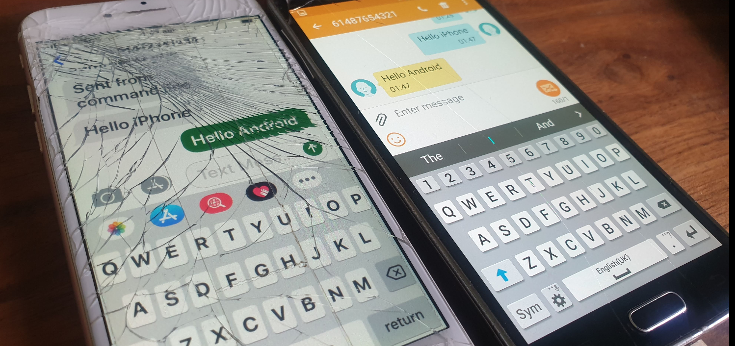
One nifty feature of this interface is that you can send SMS using the MSC to switch the SMS traffic and the LTE/EUTRAN to transfer the messaging.
This means you don’t need Circuit Switched Fallback to send or receive SMS on LTE.
I assume this functionality was added to avoid the signalling load of constantly changing RAN technologies each time a subscriber sent or received an SMS, but I couldn’t find much about it’s history.
In order to get this to work you’ll essentially need the exact same setup I outlined in my CSFB example (Osmo-MSC, Osmo-STP, Osmo-HLR populated with the IMSI and MSISDN values you want to use for SMS), although you won’t actually need a GERAN / GSM radio network.
Once that’s in place you can just send SMS between subscribers,
Plus from the VTY terminal of OsmoMSC you can send SMS too:
I’ve talked about how LTE’s EUTRAN / EPC has no knowledge about voice calls or SMS and instead relies on IMS/VoLTE for these services.
Circuit Switched Fallback allows UEs to use a 2G or 3G network (Circuit Switched network) if their device isn’t connected to the IMS network to make calls as the 2G/3G network can handle the voice call or SMS routing via the Mobile Switching Center in the 2G/3G network.
However for incoming calls destined to the UE (Mobile Terminated) the MSC needs a way to keep track of which MME is serving the UE so it can get a message to the MME and the MME can relay it to the UE, to tell it to drop to a 2G or 3G network (Circuit Switched network).
The signalling between the MME (In the LTE EPC) and the MSC (In the GSM/UTRAN core) is done over the SGs interface.
While the SGs interface is primarily for managing user location state across multiple RAN types, it’s got a useful function for sending SMS over SGi, allowing users on an LTE RAN to send SMS via the MSC of the 2G/3G network (GSM/UTRAN core).
How it Works:
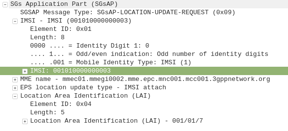
When a UE connects to the LTE RAN (EUTRAN) the MME signals the GSM/UMTS MSC with an SGsAP-LOCATION-UPDATE-REQUEST,
This request includes the IMSI of the subscriber that just attached and the FQDN of the MME serving that UE.
The MSC now knows that IMSI 001010000000003 is currently on LTE RAN served by MME mmec01.mmegi0002.mme.epc.mnc001.mcc001.3gppnetwork.org,
If a call or SMS comes into the MSC destined for the MSISDN of that IMSI, the MSC can page the UE on the LTE RAN to tell it to do an inter-RAN handover to GSM/UMTS.
Setting it Up
In order to get this working you’ll need OsmoMSC in place, your subscribers to exist on OsmoHLR and the LTE HSS – For example Open5GS-HSS.
Once you’ve done that the additional config on OsmoMSC is fairly simple, we just define a new SGs interface to listen on:
OsmoMSC Config:
sgs
  local-port 29118
  local-ip 0.0.0.0
  vlr-name vlr.msc001.mnc001.mcc001.3gppnetwork.org
end
On the Open5GS side we’ve got to include the SGs info the MME config. Keep in mind the Tracking Area Code (TAC) in LTE must exist as the Location Area code (LAC) in GSM, here’s an extract of the MME section of YAML config in the Open5GS MME config:
The EUTRAN will need to advertise the presence of it’s GERAN neighbours and vise-versa so the UE/terminals know what ARFCN to move to so they don’t need to scan for the presence of other RATs when performing the handover.
Setting this up will depend on your eNB / BSC and goes beyond the scope of this post.
I’ll cover setting up neighbours in a later post as it’s a big topic.
If you don’t have neighbours configured, the handover will still work but will be much slower as the UE will have to scan to find the serving cell it’s reselecting to.
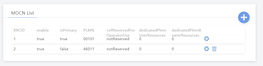
MOCN is one of those great concepts I’d not really come across,
Multi-tenancy on the RAN side of the network, allowing an eNB to broadcast multiple PLMN IDs (MCC/MNC) in the System Information Block (SIB).
It allows site sharing not just on the tower itself, but site sharing on the RAN side, allowing customers of MNO A to see themselves connected to MNO A, and customers from MNO B see themselves as connected to MNO B, but they’re both connected to the same RAN hardware.
Setup in my lab was a breeze; your RAN hardware will probably be different.
In terms of signaling it’s a standard S1AP Setup Request except with multiple broadcast PLMN keys:
I’ve been working for some time on open source mobile network cores, and one feature that has been a real struggle for a lot of people (Myself included) is getting VoLTE / IMS working.
Here’s some of the issues I’ve faced, and the lessons I learned along the way,
Sadly on most UEs / handsets, there’s no “Make VoLTE work now” switch, you’ve got a satisfy a bunch of dependencies in the OS before the baseband will start sending SIP anywhere.
Get the right Hardware
Your eNB must support additional bearers (dedicated bearers I’ve managed to get away without in my testing) so the device can setup an APN for the IMS traffic.
Sadly at the moment this rules our Software Defined eNodeBs, like srsENB.
ISIM – When you thought you understood USIMs – Guess again
According to the 3GPP IMS docs, an ISIM (IMS SIM) is not a requirement for IMS to work.
However in my testing I found Android didn’t have the option to enable VoLTE unless an ISIM was present the first time.
In a weird quirk I found once I’d inserted an ISIM and connected to the VoLTE network, I could put a USIM in the UE and also connect to the VoLTE network.
Obviously the parameters you can set on the USIM, such as Domain, IMPU, IMPI & AD, are kind of “guessed” but the AKAv1-MD5 algorithm does run.
Getting the APN Config Right
There’s a lot of things you’ll need to have correct on your UE before it’ll even start to think about sending SIP messaging.
I was using commercial UE (Samsung handsets) without engineering firmware so I had very limited info on what’s going on “under the hood”. There’s no “Make VoLTE do” tickbox, there’s VoLTE enable, but that won’t do anything by default.
If your P-GW doesn’t know the IP of your P-CSCF, it’s not going to be able to respond to it in the Protocol Configuration Options (PCO) request sent by the UE with that nice new bearer for IMS we just setup.
There’s no way around Mutual Authentication
Coming from a voice background, and pretty much having RFC 3261 tattooed on my brain, when I finally got the SIP REGISTER request sent to the Proxy CSCF I knocked something up in Kamailio to send back a 200 OK, thinking that’d be the end of it.
For any other SIP endpoint this would have been fine, but IMS Clients, nope.
Reading the specs drove home the same lesson anyone attempting to setup their own LTE network quickly learns – Mutual authentication means both the network and the UE need to verify each other, while I (as the network) can say the UE is OK, the UE needs to check I’m on the level.
I saw my 401 response go back to the UE and then no response. Nada.
This led to my next lesson…
There’s no way around IPsec
According to the 3GPP docs, support for IPsec is optional, but I found this not to be the case on the handsets I’ve tested.
After sending back my 401 response the UE looks for the IPsec info in the 401 response, then tries to setup an IPsec SA and sends ESP packets back to the P-CSCF address.
Even with my valid AKAv1-MD5 auth, I found my UE wasn’t responding until I added IPsec support on the P-CSCF, hence why I couldn’t see the second REGISTER with the Authentication Info.
After setting up IPsec support, I finally saw the UE’s REGISTER with the AKAv1-MD5 authentication, and was able to send a 200 OK.
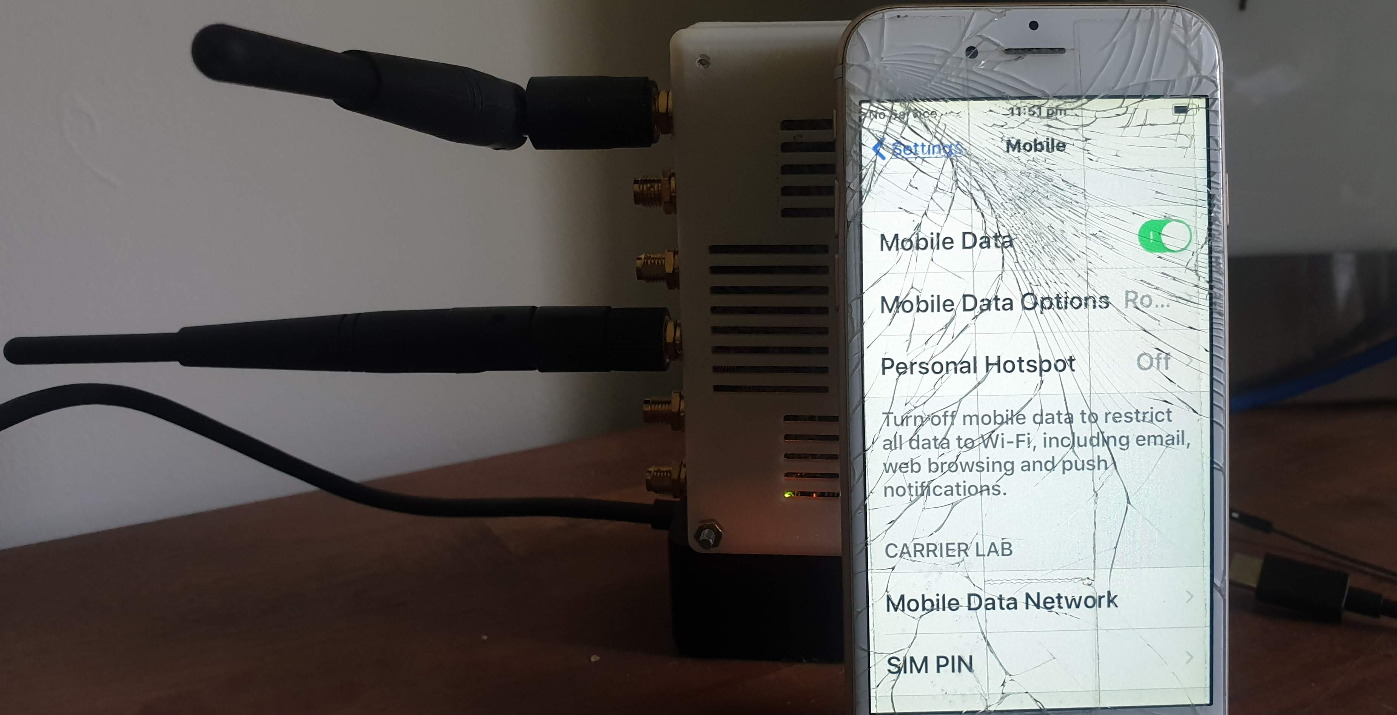
For my LTE lab I got myself a BaiCells Neutrino, it operates on Band 3 (FDD ~1800Mhz) with only 24dBm of output power max and PoE powered it works well in a lab environment without needing -48vDC supply, BBUs, DUs feeders and antennas.
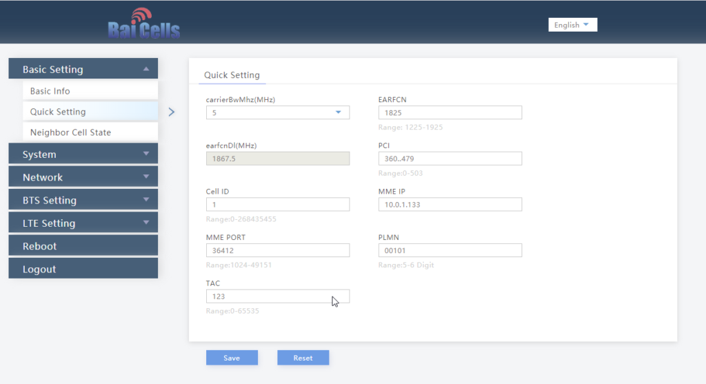
Setup can be done via TR-069 or via BaiCells management server, for smaller setups the web UI makes setup pretty easy,
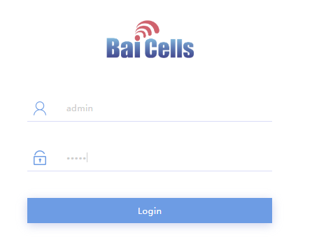
Logging in with admin/admin to the web interface:
We’ll select Quick Settings, and load in our MME IP address, PLMN (MCC & MNC), Tracking Area Code, Cell ID and Absolute Radio Frequency No.
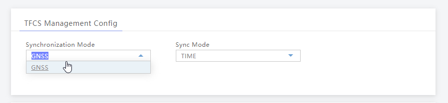
Once that’s done we’ll set our Sync settings to use GPS / GNSS (I’ve attached an external GPS Antenna purchased cheaply online).
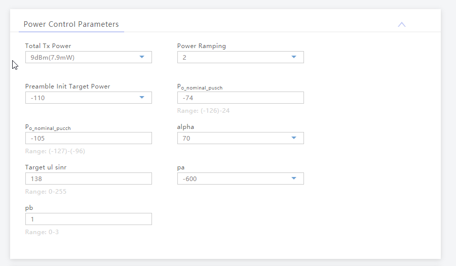
Finally we’ll set the power levels, my RF blocking setup is quite small so I don’t want excess power messing around with it, so I’ve dialed the power right back:
And that’s it, it’ll now connect to my MME on 10.0.1.133 port 36412 on SCTP.
The Proxy-Call Session Control Function is the first network element a UE sends it’s SIP REGISTER message to, but how does it get there?
To begin with our UE connects as it would normally, getting a default bearer, an IP address and connectivity.
Overview
If the USIM has an ISIM application on it (or IMS is enabled on the UE using USIM for auth) and an IMS APN exists on the UE for IMS, the UE will set up another bearer in addition to the default bearer.
This bearer will carry our IMS traffic and allow QoS to be managed through the QCI values set on the bearer.
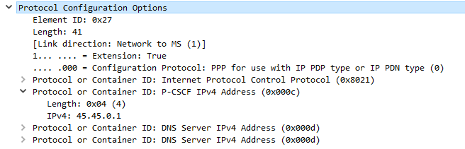
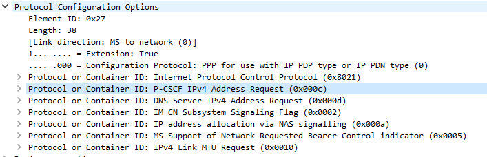
While setting up the bearer the UE requests certain parameters from the network in the Protocol Configuration Options element, including the P-CSCF address.
When setting up the bearer the network responds with this information, which if supported includes the P-CSCF IPv4 &/or IPv6 addresses.
The Message Exchange
We’ll start assuming the default bearer is in place & our UE is configured with the APN for IMS and supports IMS functionality.
The first step is to begin the establishment of an additional bearer for the IMS traffic.
This is kicked off through the Uplink NAS Transport, PDN Connectivity Request from the UE to the network. This includes the IMS APN information, and the UE’s NAS Payload includes the Protocol Configuration Options element (PCO), with a series of fields the UE requires responses from the network. including DNS Server, MTU, etc.
In the PCO the UE also includes the P-CSCF address request, so the network can tell the UE the IP of the P-CSCF to use.
If this is missing it’s because either your APN settings for IMS are not valid, or your device doesn’t have IMS support or isn’t enabling it.(that could be for a few reasons).
Protocol Configuration Options (Unpopulated) used to request information from the Network by the UE
The MME gets this information from the P-GW, and the network responds in the E-RAB Setup Request, Activate default EPS bearer Context Request and includes the Protocol Configuration Options again, this time the fields are populated with their respective values, including the P-CSCF Address;
Once the UE has this setup, the eNB confirms it’s setup the radio resources through the E-RAB Setup Response.
One the eNB has put the radio side of things in place, the UE confirms the bearer assignment has completed successfully through the Uplink NAS Transport, Activate default EPS Bearer Accept, denoting the bearer is now in place.
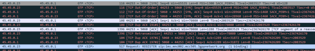
Now the UE has the IP address(s) of the P-CSCF and a bearer to send it over, the UE establishes a TCP socket with the address specified in the P-CSCF IPv4 or IPv6 address, to start communicating with the P-CSCF.
The SIP REGISTER request can now be sent and the REGISTRATION procedure can begin.
The team at Software Radio Systems in Ireland have been working on an open source LTE stack for some time, to be used with software defined radio (SDR) hardware like the USRP, BladeRF and LimeSDR.
They’ve released SRSUE and SRSENB their open source EUTRAN UE and eNodeB, which allow your SDR hardware to function as a LTE UE and connect to a commercial eNB like a standard UE while getting all the juicy logs and debug info, or as a LTE eNB and have commercial UEs connect to a network you’re running, all on COTS hardware.
The eNB supports S1AP to connect to a 3GPP compliant EPC, like Open5Gs, but also comes bundled with a barebones EPC for testing.
The UE allows you to do performance testing and gather packet captures on the MAC & PHY layers, something you can’t do on a commericial UE. It also supports software-USIMs (IMSI / K / OP variables stored in a text file) or physical USIMs using a card reader.
I’ve got a draw full of SDR hardware, from the first RTL-SDR dongle I got years ago, to a few HackRFs, a LimeSDR up to the BladeRF x40.
Really cool software to have a play with, I’ve been using SRSUE to get a better understanding of the lower layers of the Uu interface.
Installation
After mucking around trying to satisfy all the dependencies from source I found everything I needed could be found in Debian packages from the repos of the maintainers.
To begin with we need to install the BladeRF drivers and SopySDR modules to abstract it to UHD:
For most Voice / Telco engineers IPsec is a VPN technology, maybe something used when backhauling over an untrusted link, etc, but voice over IP traffic is typically secured with TLS and SRTP.
IMS / Voice over LTE handles things a bit differently, it encapsulates the SIP & RTP traffic between the UE and the P-CSCF in IPsec Encapsulating Security Payload (ESP) payloads.
In this post we’ll take a look at how it works and what it looks like.
It’s worth noting that Kamailio recently added support for IPsec encapsulation on a P-CSCF, in the IMS IPSec-Register module. I’ll cover usage of this at a later date.
The Message Exchange
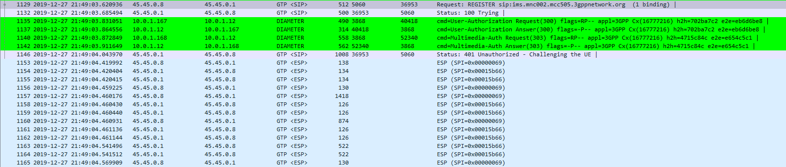
The exchange starts off looking like any other SIP Registration session, in this case using TCP for transport. The UE sends a REGISTER to the Proxy-CSCF which eventually forwards the request through to a Serving-CSCF.
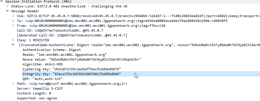
This is where we diverge from the standard SIP REGISTER message exchange. The Serving-CSCF generates a 401 Unauthorized response, containing an authentication challenge in the WWW-Authenticate header, and also a Ciphering Key & Integrity Key (ck= and ik=) also in the WWW-Authenticate header.
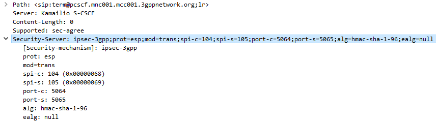
The Serving-CSCF sends the Proxy-CSCF the 401 response it created. The Proxy-CSCF assigns a SPI for the IPsec ESP to use, a server port and client port and indicates the used encryption algorithm (ealg) and algorithm to use (In this case HMAC-SHA-1-96.) and adds a new header to the 401 Unauthorized called Security–Server header to share this information with the UE.
The Proxy-CSCF also strips the Ciphering Key (ck=) and Integrity Key (ik=) headers from the SIP authentication challenge (WWW-Auth) and uses them as the ciphering and integrity keys for the IPsec connection.
Finally after setting up the IPsec server side of things, it forwards the 401 Unauthorized response onto the UE.
Upon receipt of the 401 response, the UE looks at the authentication challenge.
If the network is considered authenticated by the UE it generates a response to the Authentication Challenge, but it doesn’t deliver it over TCP. Using the information generated in the authentication challenge the UE encapsulates everything from the network layer (IPv4) up and sends it to the P-CSCF in an IPsec ESP.
Communication between the UE and the P-CSCF is now encapsulated in IPsec.
Wireshark trace of IPsec IMS Traffic between UE and P-CSCF
IPsec ESP can be used in 3 different ways on the Gm interface between the Ue and the P-CSCF:
Integrity Protection – To prevent tampering
Ciphering – To prevent inception / eavesdropping
Integrity Protection & Ciphering
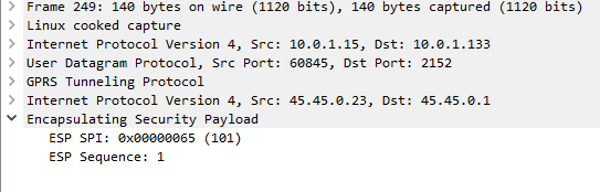
On Wireshark, you’ll see the ESP, but you won’t see the payload contents, just the fact it’s an Encapsulated Security Payload, it’s SPI and Sequence number.
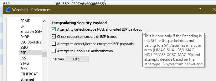
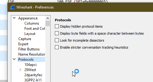
By default, Kamailio’s P-CSCF only acts in Integrity Protection mode, meaning the ESP payloads aren’t actually encrypted, with a few clicks we can get Wireshark to decode this data;
Just open up Wireshark Preferences, expand Protocols and jump to ESP
Now we can set the decoding preferences for our ESP payloads,
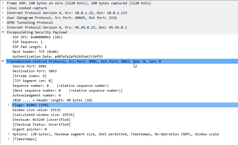
In our case we’ll tick the “Attempt to detect/decode NULL encrypted ESP payloads” box and close the box by clicking OK button.
Now Wireshark will scan through all the frames again, anything that’s an ESP payload it will attempt to parse.
Now if we go back to the ESP payload with SQN 1 I showed a screenshot of earlier, we can see the contents are a TCP SYN.
Now we can see what’s going on inside this ESP data between the P-CSCF and the UE!
As a matter of interest if you can see the IK and CK values in the 401 response before they’re stripped you can decode encrypted ESP payloads from Wireshark, from the same Protocol -> ESP section you can load the Ciphering and Integrity keys used in that session to decrypt them.
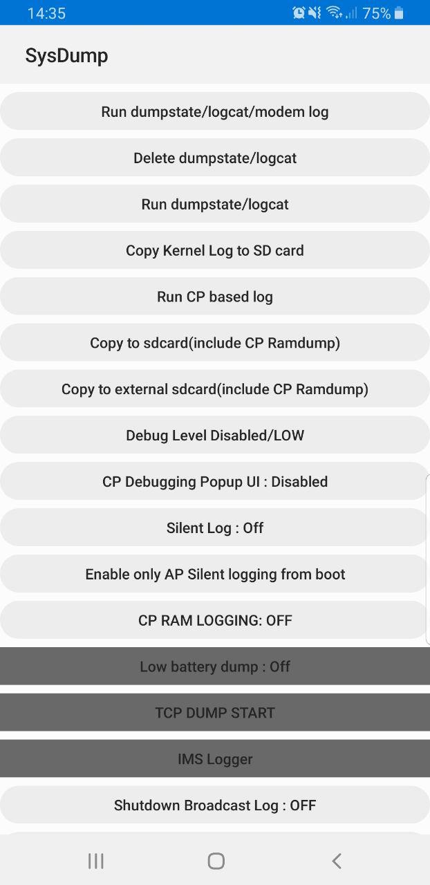
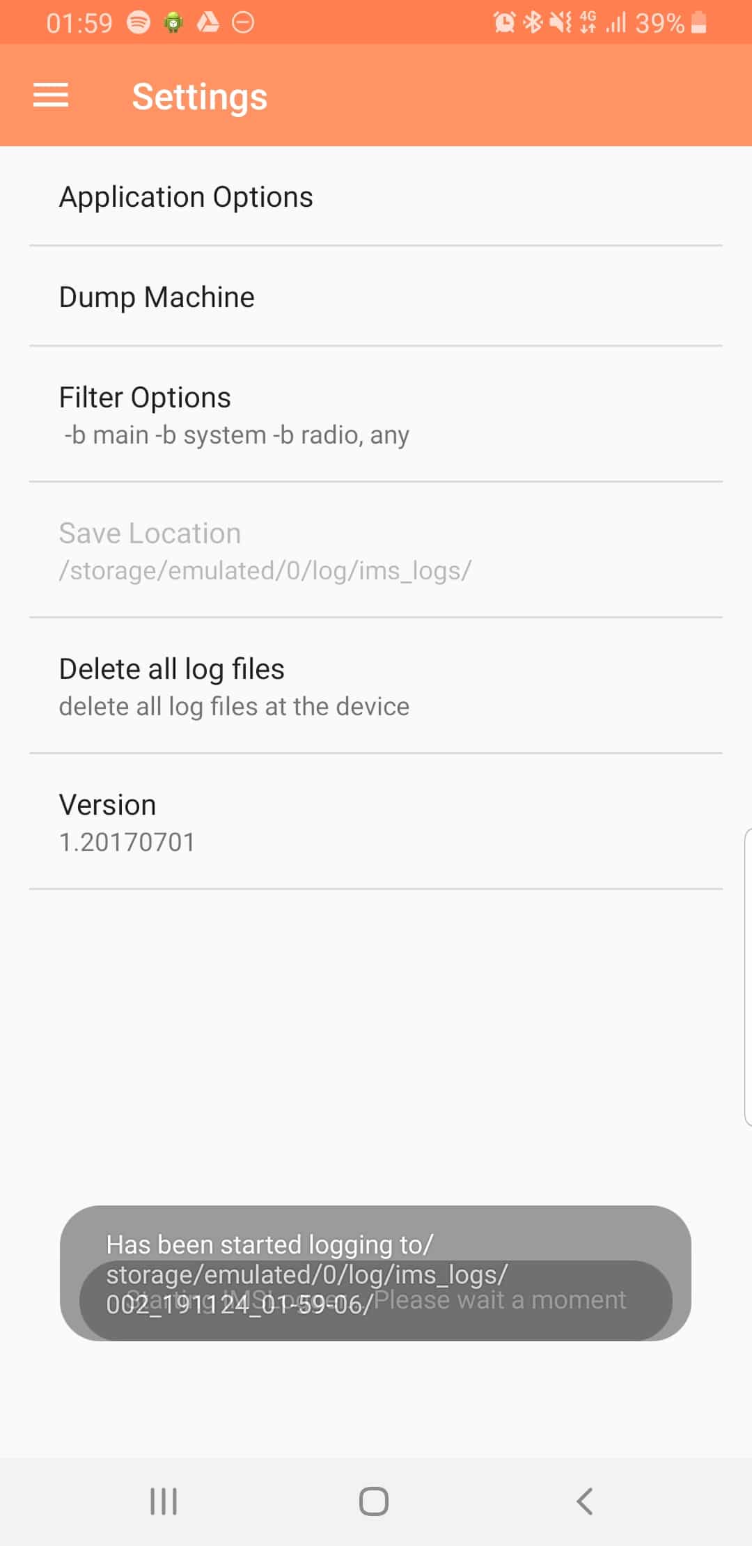
Samsung handsets have a feature built in to allow debugging from the handset, called Sysdump.
Entering *#9900# from the Dialing Screen will bring up the Sysdump App, from here you can dump logs from the device, and run a variety of debugging procedures.
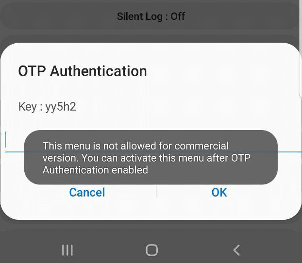
But for private LTE operators, the two most interesting options are by far the TCPDUMP START option and IMS Logger, but both are grayed out.
Tapping on them asks for a one-time password and has a challenge key.
These options are not available in the commercial version of the OS and need to be unlocked with a one time key generated by a tool Samsung for unlocking engineering firmware on handsets.
Luckily this authentication happens client side, which means we can work out the password it’s expecting.
Once you’ve entered the code and successfully unlocked the IMS Debugging tool there’s a few really cool features in the hamburger menu in the top right.
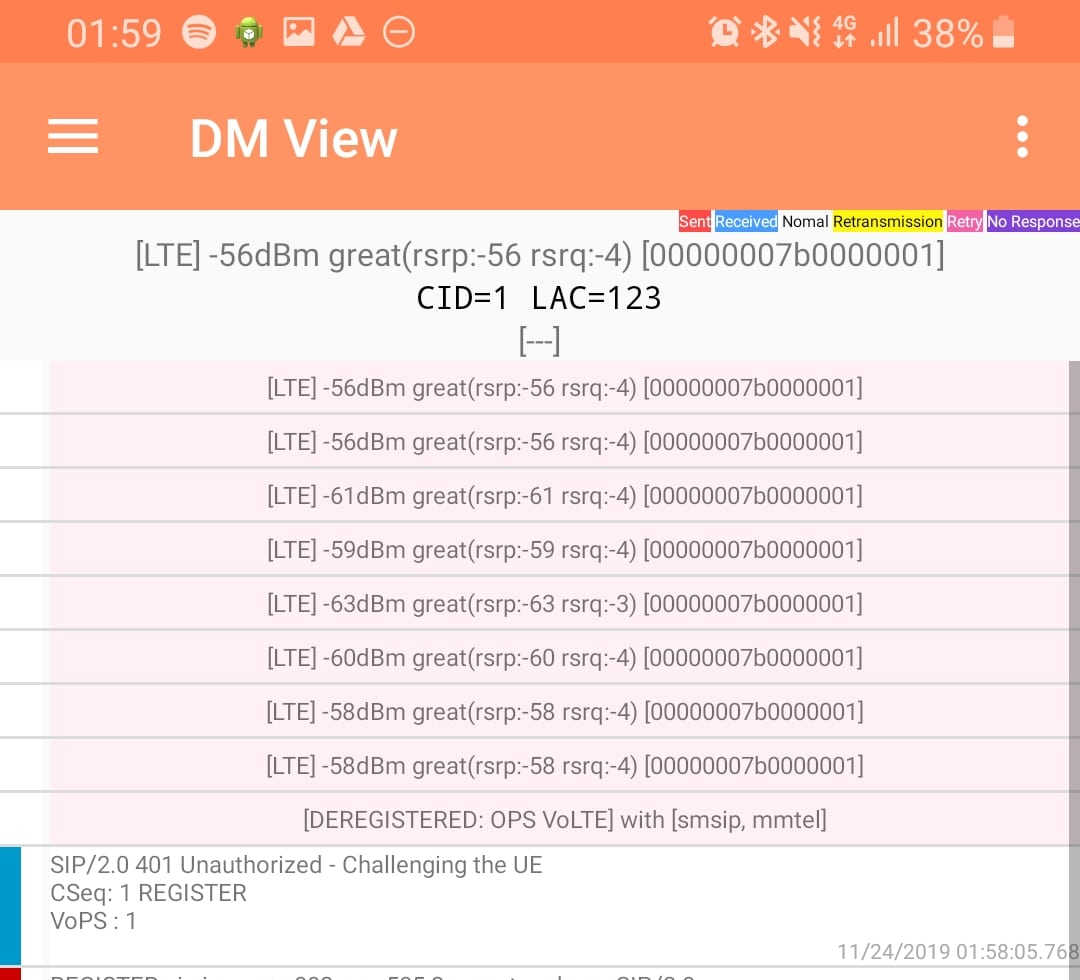
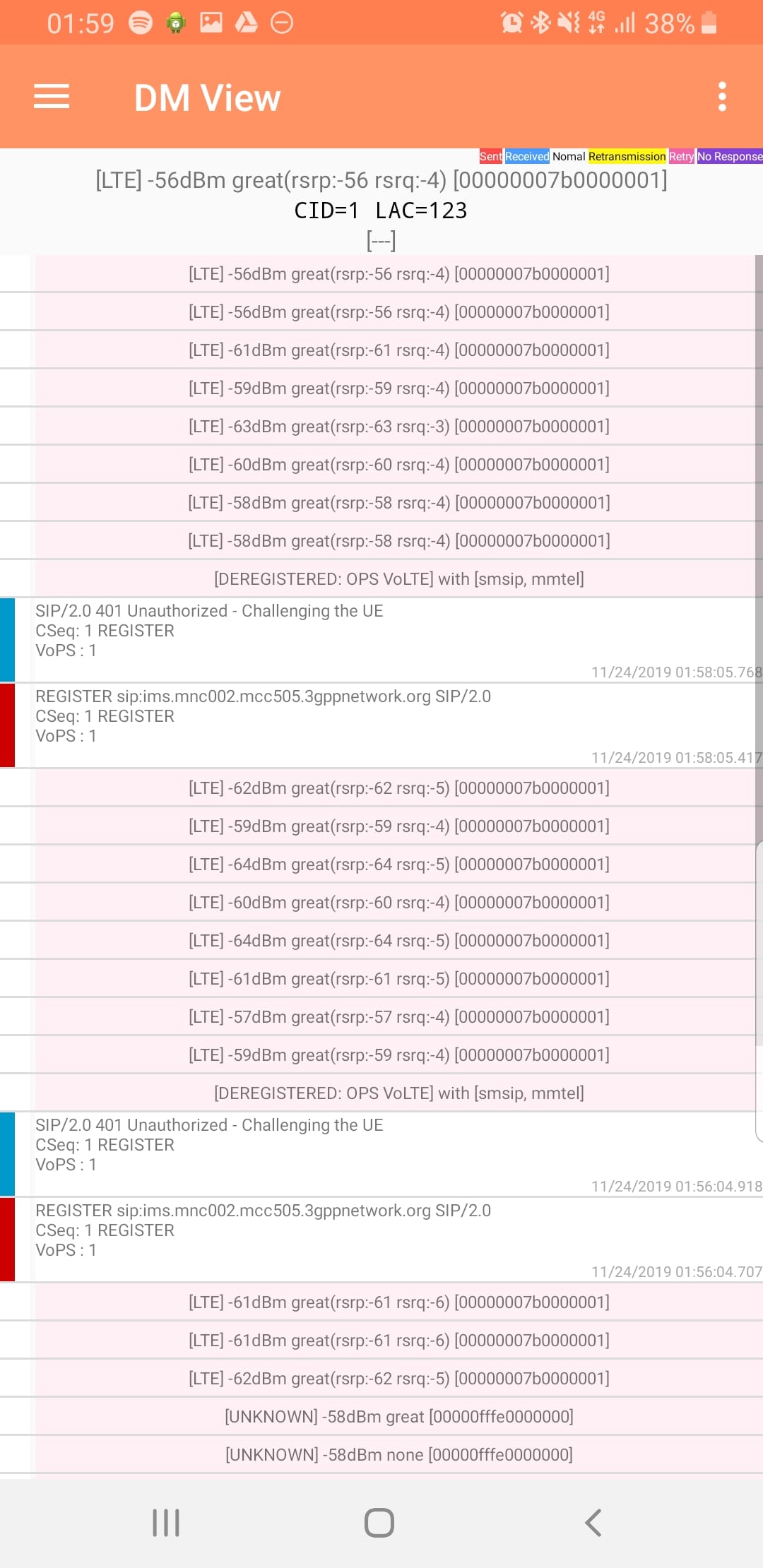
DM View
This shows the SIP / IMS Messaging and the current signal strength parameters (used to determine which RAN type to use (Ie falling back from VoLTE to UMTS / Circuit Switched when the LTE signal strength drops).
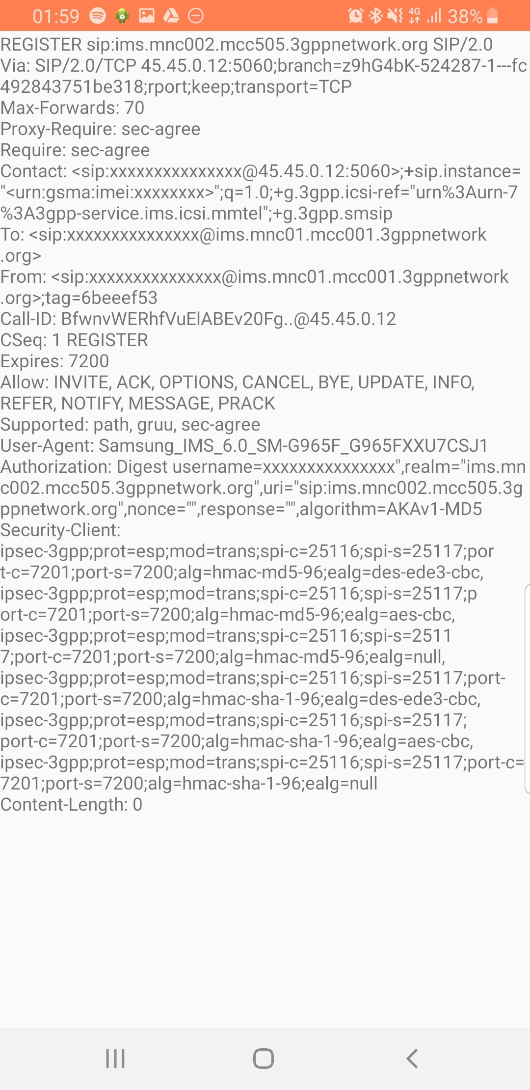
Tapping on the SIP messages expands them and allows you to see the contents of the SIP messages.
Viewing SIP Messaging directly from the handset
Interesting the actual nitty-gritty parameters in the SIP headers are missing, replaced with X for anything “private” or identifiable.
Luckily all this info can be found in the Pcap.
The DM View is great for getting a quick look at what’s going on, on the mobile device itself, without needing a PC.
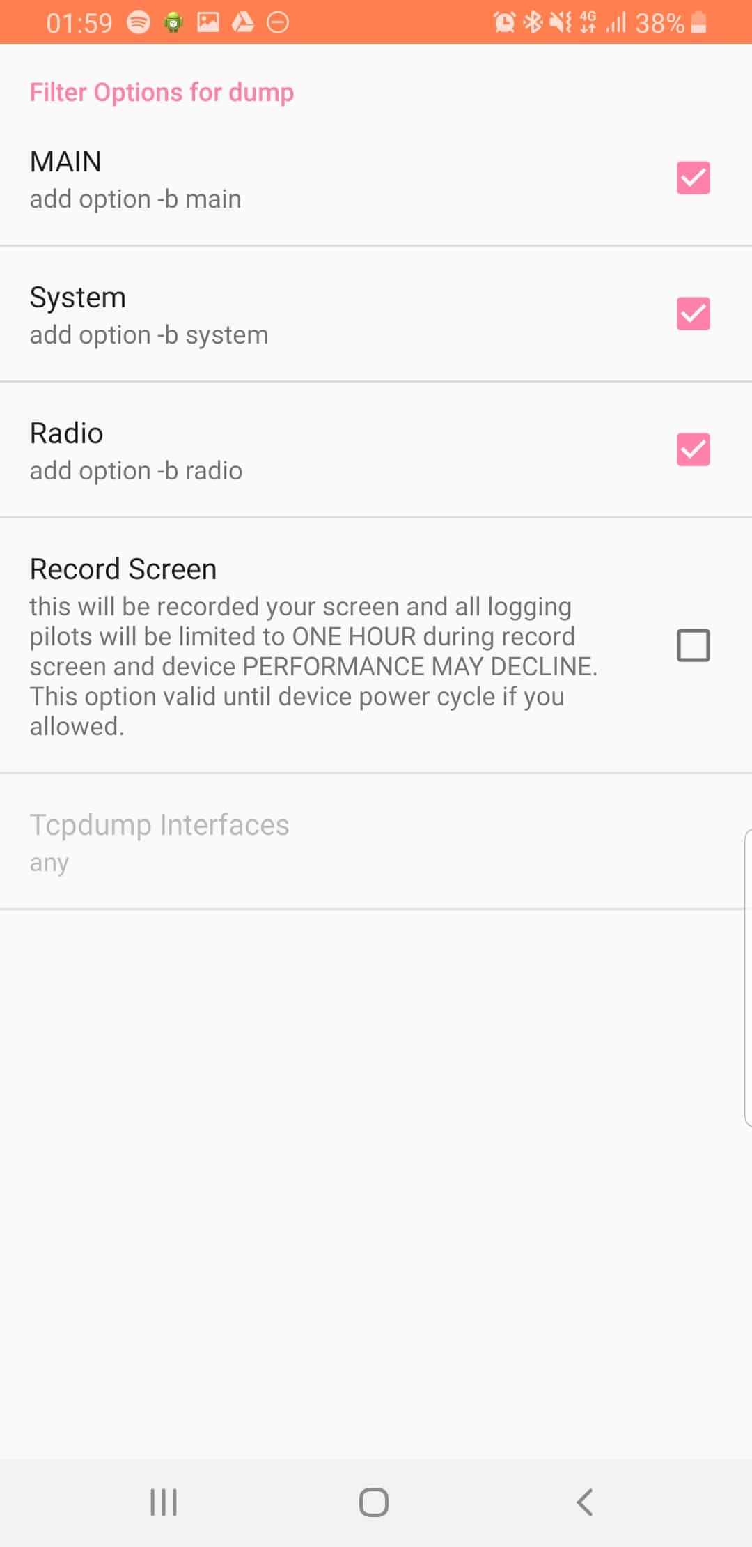
Logging
The real power comes in the logging functions,
There’s a lot of logging options, including screen recording, TCPdump (as in Packet Captures) and Syslog logging.
From the hamburger menu we can select the logging parameters we want to change.
From the Filter Options menu we can set what info we’re going to log,
The PLMN Identifier is used to identify the radio networks in use, it’s made up of the MCC – Mobile Country Code and MNC – Mobile Network Code.
But sadly it’s not as simple as just concatenating MCC and MNC like in the IMSI, there’s a bit more to it.
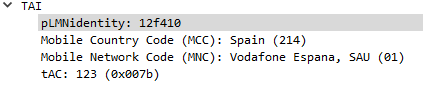
In the example above the Tracking Area Identity includes the PLMN Identity, and Wireshark has been kind enough to split it out into MCC and MNC, but how does it get that from the value 12f410?
This one took me longer to work out than I’d like to admit, and saw me looking through the GSM spec, but here goes:
PLMN Contents: Mobile Country Code (MCC) followed by the Mobile Network Code (MNC). Coding: according to TS GSM 04.08 [14].
If storage for fewer than the maximum possible number n is required, the excess bytes shall be set to ‘FF’. For instance, using 246 for the MCC and 81 for the MNC and if this is the first and only PLMN, the contents reads as follows: Bytes 1-3: ’42’ ‘F6′ ’18’ Bytes 4-6: ‘FF’ ‘FF’ ‘FF’ etc.
TS GSM 04.08 [14].
Making sense to you now? Me neither.
Here’s the Python code I wrote to encode MCC and MNCs to PLMN Identifiers and to decode PLMN into MCC and MNC, and then we’ll talk about what’s happening:
In the above example I take MCC 505 (Australia) and MCC 93 and generate the PLMN ID 05f539.
The first step in decoding is to take the first two bits (in our case 05 and reverse them – 50, then we take the third and fourth bits (f5) and reverse them too, and strip the letter f, now we have just 5. We join that with what we had earlier and there’s our MCC – 505.
Next we get our MNC, for this we take bytes 5 & 6 (39) and reverse them, and there’s our MNC – 93.
Together we’ve got MCC 505 and MNC 93.
The one answer I’m still looking for; why not just encode 50593? What is gained by encoding it as 05f539?
After a few quiet months I’m excited to say I’ve pushed through some improvements recently to PyHSS and it’s growing into a more usable HSS platform.
MongoDB Backend
This has a few obvious advantages – More salable, etc, but also opens up the ability to customize more of the subscriber parameters, like GBR bearers, etc, that simple flat text files just wouldn’t support, as well as the obvious issues with threading and writing to and from text files at scale.
Knock knock.
Race condition.
Who’s there?
— Threading Joke.
For now I’m using the Open5GS MongoDB schema, so the Open5Gs web UI can be used for administering the system and adding subscribers.
The CSV / text file backend is still there and still works, the MongoDB backend is only used if you enable it in the YAML file.
The documentation for setting this up is in the readme.
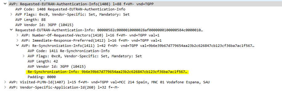
SQN Resync
If you’re working across multiple different HSS’ or perhaps messing with some crypto stuff on your USIM, there’s a chance you’ll get the SQN (The Sequence Number) on the USIM out of sync with what’s on the HSS.
This manifests itself as an Update Location Request being sent from the UE in response to an Authentication Information Answer and coming back with a Re-Syncronization-Info AVP in the Authentication Info AVP. I’ll talk more about how this works in another post, but in short PyHSS now looks at this value and uses it combined with the original RAND value sent in the Authentication Information Answer, to find the correct SQN value and update whichever database backend you’re using accordingly, and then send another Authentication Information Answer with authentication vectors with the correct SQN.
SQN Resync is something that’s really cryptographically difficult to implement / confusing, hence this taking so long.
What’s next? – IMS / Multimedia Auth
The next feature that’s coming soon is the Multimedia Authentication Request / Answer to allow CSCFs to query for IMS Registration and manage the Cx and Dx interfaces.
Code for this is already in place but failing some tests, not sure if that’s to do with the MAA response or something on my CSCFs,