Category Archives: EPC

A very unstable Diameter Routing Agent (DRA) with Kamailio

I’d been trying for some time to get Kamailio acting as a Diameter Routing Agent with mixed success, and eventually got it working, after a few changes to the codebase of the ims_diameter_server module.

It is rather unstable, in that if it fails to dispatch to a Diameter peer, the whole thing comes crumbling down, but incoming Diameter traffic is proxied off to another Diameter peer, and Kamailio even adds an extra AVP.

Having used Kamailio for so long I was really hoping I could work with Kamailio as a DRA as easily as I do for SIP traffic, but it seems the Diameter module still needs a lot more love before it’ll be stable enough and simple enough for everyone to use.

I created a branch containing the fixes I made to make it work, and with an example config for use, but use with caution. It’s a long way from being production-ready, but hopefully in time will evolve.

https://github.com/nickvsnetworking/kamailio/tree/Diameter_Fix

PyHSS Update – YAML Config Files

One feature I’m pretty excited to share is the addition of a single config file for defining how PyHSS functions,

In the past you’d set variables in the code or comment out sections to change behaviour, which, let’s face it – isn’t great.

Instead the config.yaml file defines the PLMN, transport time (TCP or SCTP), the origin host and realm.

We can also set the logging parameters, SNMP info and the database backend to be used,

HSS Parameters
 hss:
   transport: "SCTP"
   #IP Addresses to bind on (List) - For TCP only the first IP is used, for SCTP all used for Transport (Multihomed).
   bind_ip: ["10.0.1.252"]
 #Port to listen on (Same for TCP & SCTP)
   bind_port: 3868
 #Value to populate as the OriginHost in Diameter responses
   OriginHost: "hss.localdomain"
 #Value to populate as the OriginRealm in Diameter responses
   OriginRealm: "localdomain"
 #Value to populate as the Product name in Diameter responses
   ProductName: "pyHSS"
 #Your Home Mobile Country Code (Used for PLMN calcluation)
   MCC: "999"
   #Your Home Mobile Network Code (Used for PLMN calcluation)
   MNC: "99"
 #Enable GMLC / SLh Interface
   SLh_enabled: True


 logging:
   level: DEBUG
   logfiles:
     hss_logging_file: log/hss.log
     diameter_logging_file: log/diameter.log
     database_logging_file: log/db.log
   log_to_terminal: true

 database:
   mongodb:
     mongodb_server: 127.0.0.1
     mongodb_username: root
     mongodb_password: password
     mongodb_port: 27017

 Stats Parameters
 redis:
   enabled: True
   clear_stats_on_boot: False
   host: localhost
   port: 6379
 snmp:
   port: 1161
   listen_address: 127.0.0.1
MSISDN Encoding - Brought to you by the letter F

MSISDN Encoding in Diameter AVPs – Brought to you by the letter F

So this one knocked me for six the other day,

MSISDN AVP 700 / vendor ID 10415, used to advertise the subscriber’s MSISDN in signaling.

I formatted the data as an Octet String, with the MSISDN from the database and moved on my merry way.

Not so fast…

The MSISDN AVP is of type OctetString.

This AVP contains an MSISDN, in international number format as described in ITU-T Rec E.164 [8], encoded as a TBCD-string, i.e. digits from 0 through 9 are encoded 0000 to 1001;

1111 is used as a filler when there is an odd number of digits; bits 8 to 5 of octet n encode digit 2n; bits 4 to 1 of octet n encode digit 2(n-1)+1.

ETSI TS 129 329 / 6.3.2 MSISDN AVP

Come again?

In practice this means if you have an odd lengthed MSISDN value, we need to add some padding to round it out to an even-lengthed value.

This padding happens between the last and second last digit of the MSISDN (because if we added it at the start we’d break the Country Code, etc) and as MSISDNs are variable length subscriber numbers.

1111 in octet string is best known as the letter F,

Not that complicated, just kind of confusing.

PyHSS Update – SCTP Support

Pleased to announce that PyHSS now supports SCTP for transport.

If you’re not already aware SCTP is the surprisingly attractive cousin of TCP, that addresses head of line blocking and enables multi-homing,

The fantastic PySCTP library from P1sec made adding this feature a snap. If you’re looking to add SCTP to a Python project, it’s surprisingly easy,

A seperate server (hss_sctp.py) is run to handle SCTP connections, and if you’re looking for Multihoming, we got you dawg – Just edit the config file and set the bind_ip list to include each of your IPs to multi home listen on.

And the call was coming from… INSIDE THE HOUSE. A look at finding UE Locations in LTE

Opening Tirade

Ok, admittedly I haven’t actually seen “When a Stranger Calls”, or the less popular sequel “When a stranger Redials” (Ok may have made the last one up).

But the premise (as I read Wikipedia) is that the babysitter gets the call on the landline, and the police trace the call as originating from the landline.

But you can’t phone yourself, that’s not how local loops work – When the murderer goes off hook it loops the circuit, which busys it. You could apply ring current to the line I guess externally but unless our murder has a Ring generator or has setup a PBX inside the house, the call probably isn’t coming from inside the house.

On Topic – The GMLC

The GMLC (Gateway Mobile Location Centre) is a central server that’s used to locate subscribers within the network on different RATs (GSM/UMTS/LTE/NR).

The GMLC typically has interfaces to each of the radio access technologies, there is a link between the GMLC and the CS network elements (used for GSM/UMTS) such as the HLR, MSC & SGSN via Lh & Lg interfaces, and a link to the PS network elements (LTE/NR) via Diameter based SLh and SLg interfaces with the MME and HSS.

The GMLC’s tentacles run out to each of these network elements so it can query them as to a subscriber’s location,

LTE Call Flow

To find a subscriber’s location in LTE Diameter based signaling is used, to query the MME which in turn queries, the eNodeB to find the location.

But which MME to query?

The SLh Diameter interface is used to query the HSS to find out which MME is serving a particular Subscriber (identified by IMSI or MSISDN).

The LCS-Routing-Info-Request is sent by the GMLC to the HSS with the subscriber identifier, and the LCS-Routing-Info-Response is returned by the HSS to the GMLC with the details of the MME serving the subscriber.

Now we’ve got the serving MME, we can use the SLg Diameter interface to query the MME to the location of that particular subscriber.

The MME can report locations to the GMLC periodically, or the GMLC can request the MME provide a location at that point.
For the GMLC to request a subscriber’s current location a Provide-Location-Request is set by the GMLC to the MME with the subscriber’s IMSI, and the MME responds after querying the eNodeB and optionally the UE, with the location info in the Provide-Location-Response.

(I’m in the process of adding support for these interfaces to PyHSS and all going well will release some software shortly to act at a GMLC so people can use this.)

Finding the actual Location

There are a few different ways the actual location of the UE is determined,

At the most basic level, Cell Global Identity (CGI) gives the identity of the eNodeB serving a user.
If you’ve got a 3 sector site each sector typically has its own Cell Global Identity, so you can determine to a certain extent, with the known radiation pattern, bearing and location of the sector, in which direction a subscriber is. This happens on the network side and doesn’t require any input from the UE.
But if we query the UE’s signal strength, this can then be combined with existing RF models and the signal strength reported by the UE to further pinpoint the user with a bit more accuracy. (Uplink and downlink cell coverage based positioning methods)
Barometric pressure and humidity can also be reported by the base station as these factors will impact resulting signal strengths.

Timing Advance (TA) and Time of Arrival (TOA) both rely on timing signals to/from a UE to determine it’s distance from the eNodeB. If the UE is only served by a single cell this gives you a distance from the cell and potentially an angle inside which the subscriber is. This becomes far more useful with 3 or more eNodeBs in working range of the UE, where you can “triangulate” the UE’s location. This part happens on the network side with no interaction with the UE.
If the UE supports it, EUTRAN can uses Enhanced Observed Time Difference (E-OTD) positioning method, which does TOD calcuation does this in conjunction with the UE.

GPS Assisted (A-GPS) positioning gives good accuracy but requires the devices to get it’s current location using the GPS, which isn’t part of the baseband typically, so isn’t commonly implimented.

Uplink Time Difference of Arrival (UTDOA) can also be used, which is done by the network.

So why do we need to get Subscriber Locations?

The first (and most noble) use case that springs to mind is finding the location of a subscriber making a call to emergency services. Often upon calling an emergency services number the GMLC is triggered to get the subscriber’s location in case the call is cut off, battery dies, etc.

But GMLCs can also be used for lots of other purposes, marketing purposes (track a user’s location and send targeted ads), surveillance (track movements of people) and network analytics (look at subscriber movement / behavior in a specific area for capacity planning).

Different countries have different laws regulating access to the subscriber location functions.

Hack to disable Location Reporting on Mobile Networks

If you’re wondering how you can disable this functionality, you can try the below hack to ensure that your phone does not report your location.

  1. Press the power button on your phone
  2. Turn it off

In reality, no magic super stealth SIM cards, special phones or fancy firmware will prevent the GMLC from finding your location.
So far none of the “privacy” products I’ve looked at have actually done anything special at the Baseband level. Most are just snakeoil.

For as long as your device is connected to the network, the passive ways of determining location, such as Uplink Time Difference of Arrival (UTDOA) and the CGI are going to report your location.

MTU in LTE & 5G Transmission Networks – Part 1

Every now and then when looking into a problem I have to really stop and think about how things work low down, that I haven’t thought about for a long time, and MTU is one of those things.

I faced with an LTE MTU issue recently I thought I’d go back and brush up on my MTU knowhow and do some experimenting.

Note: This is an IPv4 discussion, IPv6 does not support fragmentation.

The very, very basics

MTU is the Maximum Transmission Unit.

In practice this is the largest datagram the layer can handle, and more often than not, this is based on a physical layer constraint, in that different physical layers can only stuff so much into a frame.

“The Internet” from a consumer perspective typically has an MTU of 1500 bytes or perhaps a bit under depending on their carrier, such as 1472 bytes.
SANs in data centers typically use an MTU of around 9000 bytes,
Out of the box, most devices if you don’t specify, will use an MTU of 1500 bytes.

As a general rule, service providers typically try to offer an MTU as close to 1500 as possible.

Messages that are longer than the Maximum Transmission Unit need to be broken up in a process known as “Fragmenting”.
Fragmenting allows large frames to be split into smaller frames to make their way across hops with a lower MTU.

All about Fragmentation

So we can break up larger packets into smaller ones by Fragmenting them, so case closed on MTU right? Sadly not.

Fragmentation leads to reduced efficiency – Fragmenting frames takes up precious CPU cycles on the router performing it, and each time a frame is broken up, additional overhead is added by the device breaking it up, and by the receiver to reassemble it.

Fragmentation can happen multiple times across a path (Multi-Stage Fragmentation).
For example if a frame is sent with a length of 9000 bytes, and needs to traverse a hop with an MTU of 4000, it would need to be fragmented (broken up) into 3 frames (Frame 1 and Frame 2 would be ~4000 bytes long and frame 3 would be ~1000 bytes long).
If it then needs to traverse another hop with an MTU of 1500, then the 3 fragmented frame would each need to be further fragmented, with the first frame of ~4000 bytes being split up into 3 more fragmented frames.
Lost track of what just happened? Spare a thought for the routers having to to do the fragmentation and the recipient having to reassemble their packets.

Fragmented frames are reassembled by the end recipient, other devices along the transmission path don’t reassemble packets.

In the end it boils down to this trade off:
The larger the packet can be, the more user data we can stuff into each one as a percentage of the overall data. We want the percentage of user data for each packet to be as high as can be.
This means we want to use the largest MTU possible, without having to fragment packets.

Overhead eats into our MTU

A 1500 byte MTU that has to be encapsulated in IPsec, GTP or PPP, is no longer a 1500 byte MTU as far as the customer is concerned.

Any of these encapsulation techniques add overhead, which shrinks the MTU available to the end customer.

Keep in mind we’re going to be encapsulating our subscriber’s data in GTP before it’s transmitted across LTE/NR, and this means we’ll be adding:

  • 8 bytes for the GTP header
  • 8 bytes for the transport UDP header
  • 20 bytes for the transport IPv4 header
  • 14 bytes if our transport is using Ethernet

This means we’ve got 50 bytes of transmission / transport overhead. This will be important later on!

How do subscribers know what to use as MTU?

Typically when a subscriber buys a DSL service or HFC connection, they’ll either get a preconfigured router from their carrier, or they will be given a list of values to use that includes MTU.

LTE and 5G on the other hand tell us the value we should use.

Inside the Protocol Configuration Options in the NAS PDU, the UE requests the MTU and DNS server to be used, and is provided back from the network.

This MTU value is actually set on the MME, not the P-GW. As the MME doesn’t actually know the maximum MTU of the network, it’s up to the operator to configure this to be a value that represents the network.

Why this Matters for LTE & 5G Transmission

As we covered earlier, fragmentation is costly. If we’re fragmenting packets we are:

  • Wasting resources on our transmission network / core networks – as we fragment Subscriber packets it’s taking up compute resources and therefore limiting throughput
  • Wasting radio resources as additional overhead is introduced for fragmented packets, and additional RBs need to be scheduled to handle the fragmented packets

To test this I’ve setup a scenario in the lab, and we’ll look at the packet captures to see how the MTU is advertised, and see how big we can make our MTU on the subscriber side.

Getting the GTP-U Packets flowing Fast – DPDK & SR-IOV

So dedicated appliances are dead and all our network functions are VMs or Containers, but there’s a performance hit when going virtual as the L2 processing has to be handled by the Hypervisor before being passed onto the relevant VM / Container.

If we have a 10Gb NIC in our server, we want to achieve a 10Gbps “Line Speed” on the Network Element / VNF we’re running on.

When we talked about appliances if you purchased an P-GW with 10Gbps NIC, it was a given you could get 10Gbps through it (without DPI, etc), but when we talk about virtualized network functions / network elements there’s a very real chance you won’t achieve the “line speed” of your interfaces without some help.

When you’ve got a Network Element like a S-GW, P-GW or UPF, you want to forward packets as quickly as possible – bottlenecks here would impact the user’s achievable speeds on the network.

To speed things up there are two technologies, that if supported by your software stack and hardware, allows you to significantly increase throughput on network interfaces, DPDK & SR-IOV.

DPDK – Data Plane Development Kit

Usually *Nix OSs handle packet processing on the Kernel level. As I type this the packets being sent to this WordPress server by Firefox are being handled by the Linux 5.8.0-36-generic kernel running on my machine.

The problem is the kernel has other things to do (interrupts), meaning increased delay in processing (due to waiting for processing capability) and decreased capacity.

DPDK shunts this processing to the “user space” meaning your application (the actual magic of the VNF / Network Element) controls it.

To go back to me writing this – If Firefox and my laptop supported DPDK, then the packets wouldn’t traverse the Linux kernel at all, and Firefox would be talking directly to my NIC. (Obviously this isn’t the case…)

So DPDK increases network performance by shifting the processing of packets to the application, bypassing the kernel altogether. You are still limited by the CPU and Memory available, but with enough of each you should reach very near to line speed.

SR-IOV – Single Root Input Output Virtualization

Going back to the me writing this analogy I’m running Linux on my laptop, but let’s imagine I’m running a VM running Firefox under Linux to write this.

If that’s the case then we have an even more convolted packet processing chain!

I type the post into Firefox which sends the packets to the Linux kernel, which waits to be scheduled resources by the hypervisor, which then process the packets in the hypervisor kernel before finally making it onto the NIC.

We could add DPDK which skips some of these steps, but we’d still have the bottleneck of the hypervisor.

With PCIe passthrough we could pass the NIC directly to the VM running the Firefox browser window I’m typing this, but then we have a problem, no other VMs can access these resources.

SR-IOV provides an interface to passthrough PCIe to VMs by slicing the PCIe interface up and then passing it through.

My VM would be able to access the PCIe side of the NIC, but so would other VMs.

So that’s the short of it, SR-IOR and DPDK enable better packet forwarding speeds on VNFs.

Power cables feeding Ericsson RBS rack

Cell Broadcast in LTE

Recently I’ve been wrapping my head around Cell Broadcast in LTE, and thought I’d share my notes on 3GPP TS 38.413.

The interface between the MME and the Cell Broadcast Center (CBC) is the SBc interface, which as two types of “Elementary Procedures”:

  • Class 1 Procedures are of the request – response nature (Request followed by a Success or Failure response)
  • Class 2 Procedures do not get a response, and are informational one-way. (Acked by SCTP but not an additional SBc message).

SCTP is used as the transport layer, with the CBC establishing a point to point connection to the MME over SCTP (Unicast only) on port 29168 with SCTP Payload Protocol Identifier 24.

The SCTP associations between the MME and the CBC should normally remain up – meaning the SCTP association / transport connection is up all the time, and not just brought up when needed.

Elementary Procedures

Write-Replace Warning (Class 1 Procedure)

The purpose of Write-Replace Warning procedure is to start, overwrite the broadcasting of warning message, as defined in 3GPP TS 23.041 [14].

Write-Replace Warning procedure, initiated by WRITE-REPLACE WARNING REQUEST sent by the CBC to the MMEs contains the emergency message to be broadcast and the parameters such as TAC to broadcast to, severity level, etc.

A WRITE-REPLACE WARNING RESPONSE is sent back by the MME to the MME, if successful, along with information as to where it was sent out. CBC messages are unacknowledged by UEs, meaning it’s not possible to confirm if a UE has actually received the message.

The request includes the message identifier and serial number, list of TAIs, repetition period, number of broadcasts requested, warning type, and of course, the warning message contents.

Stop Warning Procedure (Class 1 Procedure)

Stop Warning Procedure, initiated by STOP WARNING REQUEST and answered with a STOP WARNING RESPONSE, requests the MME inform the eNodeBs to stop broadcasting the CBC in their SIBs.

Includes TAIs of cells this should apply to and the message identifier,

Error Indication (Class 2)

The ERROR INDICATION is used to indicate an error (duh). Contains a Cause and Criticality IEs and can be sent by the MME or CBC.

Write Replace Warning (Class 2)

The WRITE REPLACE WARNING INDICATION is used to indicate warning scenarios for some instead of a WRITE-REPLACE WARNING RESPONSE,

PWS Restart (Class 2)

The PWS RESTART INDICATION is used to list the eNodeBs / cells, that have become available or have restarted, since the CBC message and have no warning message data – for example eNodeBs that have just come back online during the period when all the other cells are sending Cell Broadcast messages.

Returns a the Restarted-Cell-List IE, containing the Global eNB ID IE and List of TAI, of the restarted / reconnected cells.

PWS Failure Indication (Class 2)

The PWS FAILURE INDICATION is essentially the reverse of PWS RESTART INDICATION, indicating which eNodeBs are no longer available. These cells may continue to send Cell Broadcast messages as the MME has essentially not been able to tell it to stop.

Contains a list of Failed cells (eNodeBs) with the Global-eNodeB-ID of each.

5GC for EPC Folks – Control Plane Signalling

As the standardisation for 5G-SA has been completed and the first roll outs are happening, I thought I’d cover the basic architecture of the 5G Core Network, for people with a background in EPC/SAE networks for 4G/LTE, covering the key differences, what’s the same and what’s new.

The AMFAuthentication & Mobility Function, serves much the same role as the MME in LTE/EPC/SAE networks.

Like the MME, the AMF only handles Control Plane traffic, and serves as the gatekeeper to the services on the network, connecting the RAN to the core, authenticating subscribers and starting data / PDN connections for the UEs.

While the MME connects to eNodeBs for RAN connectivity, the AMF connects to gNodeBs for RAN.

The Authentication Functions

In EPC the HSS had two functions; it was a database of all subscribers’ profile information and also the authentication centre for generating authentication vectors.

5GC splits this back into two network elements (Akin to the AuC and HLR in 2G/3G).

The UDM (Unified Data Management) provides the AMF with the subscriber profile information (allowed / barred services / networks, etc),

The AUSF (Authentication Server Function) provides the AMF with the authentication vectors for authenticating subscribers.

Like in UMTS/LTE USIMs are used to authenticate subscribers when connecting to the network, again using AKA (Authentication and Key Agreement) for mutual subscriber & network authentication.

Other authentication methods may be implemented, R16 defines 3 suporrted methods, 5G-AKA, EAP-AKA’, and EAP-TLS.

This opens the door for the 5GC to be used for non-mobile usage. There has been early talk of using the 5G architecture for fixed line connectivity as well as mobile, hence supporting a variety of authentication methods beyond classic AKA & USIMs. (For more info about Non-3GPP Access interworking look into the N3IWF)

The Mobility Functions

When a user connects to the network the AMF selects a SMF (Session Management Function) akin to a P-GW-C in EPC CUPS architecture and requests the SMF setup a connection for the UE.

This is similar to the S11 interface in EPC, however there is no S-GW used in 5GC, so would be more like if S11 were instead sent to the P-GW-C.

The SMF selects a UPF (Akin to the P-GW-C selecting a P-GW-U in EPC), which will handle this user’s traffic, as the UPF bridges external data networks (DNs) to the gNodeB serving the UE.

More info on how the UPF functions compared to it’s EPC counterparts can be found in this post.

Moving between cells / gNodeBs is handled in much the same way as done previously, with the path the UPF sends traffic to (N3 interface) updated to point to the IP of the new gNodeB.

Mobility between EPC & 5GC is covered in this post.

Connection Overview

When a UE attempts to connect to the network their signalling traffic (Using the N1 reference point between the UE and the AMF), is sent to the AMF.

an authentication challenge is issued as in previous generations.

Upon successful authentication the AMF signals the SMF to setup a session for the UE. The SMF selects a UPF to handle the user plane forwarding to the gNodeB serving the UE.

Key Differences

  • Functions handled by the MME in EPC now handled by AMF in 5GC
  • Functions of HSS now in two Network Functions – The UDM (Unified Data Management) and AUSF (Authentication Server Function)
  • Setting up data connections “flatter” (more info on the User Plane differences can be found here)
  • Non 3GPP access (Potentially used for fixed-line / non mobile networks)

See also: 5GC for EPC Folks – User Plane Traffic

5GC for EPC Folks – User Plane Traffic

As the standardisation for 5G-SA has been completed and the first roll outs are happening, I thought I’d cover the basic architecture of the 5G Core Network, for people with a background in EPC/SAE networks for 4G/LTE, covering the key differences, what’s the same and what’s new.

This posts focuses on the User Plane side of things, there’s a similar post I’ve written here on the Control Plane side of things.

UPF – User Plane Forwarding

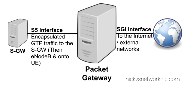
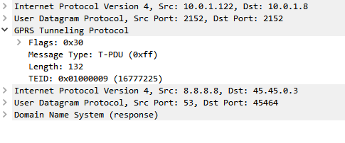
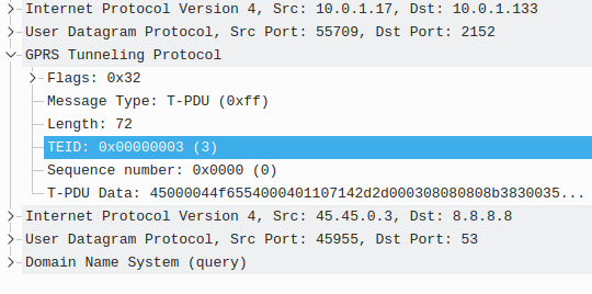
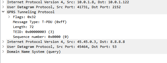
The UPF bridges the external networks (DNs) to the gNodeB serving the UE by encapsulating the traffic into GTP, which has been used in every network since GSM.

Like the P-GW the UPF takes traffic destined to/from external networks and passes it to/from subscribers.

In 5GC these external networks are now referred to as “DN” – Data Networks, instead of by the SGi reference point.

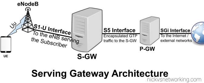
In EPC the Serving-Gateway’s intermediate function of routing traffic to the correct eNB is removed and instead this is all handled by the UPF, along with buffering packets for a subscriber in idle mode.

The idea behind this, is that by removing the S-GW removes extra hops / latency in the network, and allows users to be connected to the best UPF for their needs, typically one located close to the user.

However, there are often scenarios where an intermediate function is required – for example wanting to anchor a session to keep an IP Address allocated to one UPF associated with a user, while they move around the network. In this scenario a UPF can act as an “Session Anchor” (Akin to a P-GW), and pass through “Intermediate UPFs” (Like S-GWs).

Unlike the EPCs architecture, there is no limit to how many I-UPFs can be chained together between the Session Anchoring UPF and the gNB, and this chaining of UPFs allows for some funky routing options.

The UPF is dumb by design. The primary purpose is just to encapsulate traffic destined from external networks to subscribers into GTP-U packets and forward them onto the gNodeB serving that subscriber, and the same in reverse. Do one thing and do it well.

SMF – Session Management Function

So with dumb UPFs we need something smarter to tell them what to do.

Control of the UPFs is handled by the SMF – Session Management Function, which signals using PFCP down to the UPFs to tell them what to do in terms of setting up connections.

While GTP-U is used for handling user traffic, control plane traffic no longer uses GTPv2-C. Instead 5GC uses PFCP – Packet Forwarding Control Protocol. To get everyone warmed up to Control & User Plane separation 3GPP introduced as seen in CUPS into the EPC architecture in Release 14.

This means the interface between the SMF and UPF (the N4 interface) is more or less the same as the interface between a P-GW-C and a P-GW-U seen in CUPS.

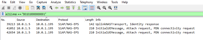
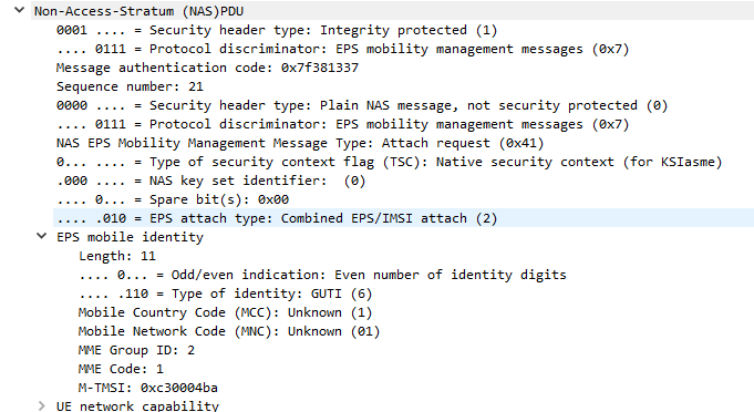
When a subscriber connects to the network and has been authenticated, the AMF (For more info on the AMF see the sister post to this topic covering Control Plane traffic) requests the SMF to setup a connection for the subscriber.

Interworking with EPC

For deployments with an EPC and 5GC interworking between the two is of course required.

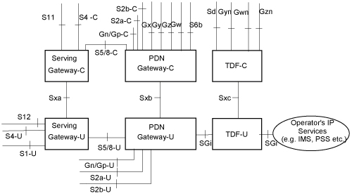
This is achieved first through the implementation of CUPS (Control & User Plane Separation) on the EPC, specifically splitting the P-GW into a P-GW-C for handing the Control Plane signalling (GTPv2c) and a P-GW-U for the User Plane traffic encapsulated into GTP.

The P-GW-C and P-GW-U communications using PFCP are essentially the same as the N4 interface (between the SMF and the UPF) so the P-GW-U is able to act as a UPF.

This means handovers between the two RATs / Cores is seamless as when moving from an LTE RAT and EPC to a 5G RAT and 5G Core, the same UPF/P-GW-U is used, and only the Control Plane signalling around it changes.

When moving from LTE to 5G RAT, the P-GW-C is replaced by the SMF,
When moving from 5G RAT to LTE, the SMF is replaced by the P-GW-C.
In both scenarios user plane traffic takes the same exit point to external Data Networks (SGi interface in EPC / N6 interface in 5GC).

Interfaces / Reference Points

N3 Interface

N3 interface connects the gNodeB user plane to the UPF, to transport GTP-U packets.

This is a User Plane interface, and only transports user plane traffic.

This is akin to the S1-UP interface in EPC.

N4 Interface

N4 interface connects the Session Management Function (SMF) control plane to the UPF, to setup, modify and delete UPF sessions.

It is a control plane interface, and does not transport User Plane traffic.

This interface relies on PFCP – Packet Forwarding Control Protocol.

This is akin to the SxB interface in EPC with CUPS.

N6 Interface

N6 interface connects the UPF to External Data Networks (DNs), taking packets destined for Subscribers and encapsulating them into GTP-U packets.

This is a User Plane interface, and only transports user plane traffic.

This is akin to the SGi interface in EPC.

N9 Interface

When Session Anchoring is used, and Intermediate-UPFs are used, the connection between these UPFs uses the N9 interface.

This is only used in certain scenarios – the preference is generally to avoid unnecessary hops, so Intermediate-UPF usage is to be avoided where possible.

As this is a User Plane interface, it only transports user plane traffic.

When used this would be akin to the S5 interface in EPC.

N11 Interface

SMFs need to be told when to setup / tear down connections, this information comes from the AMF via the N11 interface.

As this is a Control Plane interface, it only transports control plane traffic.

This is similar to the S11 interface between the MME and the S-GW in EPC, however it would be more like the S11 if the S11 terminated on the P-GW.

Packet Gateway (P-GW) used in LTE EPC Networks

LTE EPC: Packet Gateway (P-GW) Basic Function

The Packet Gateway connects users of an LTE network to external networks like the Internet, by encapsulating IP packets inside GTP and forwarding them on to reach our subscriber wherever in the network they are.

To understand the P-GW, first it’s a good idea to first get a grasp on what GTP is and why we use GTP to transport subscriber’s data through the LTE Evolved Packet Core.

So we use GTP to encapsulate user’s traffic, making it easy to carry it transparently from outside networks (Like the Internet) to the eNodeB and onto our UE / mobile phones, and more importantly redirect where the user’s traffic it’s going while keeping the same IP address.

But we need a network element to take plain old IP from external networks / Internet, and encapsulate the traffic into the GTP packets we’ll send to the subscriber.

This network element will have to do the same in reverse and decapsulate traffic coming from the subscriber to put it back onto the external networks / Internet.

That’s the role of the Packet Gateway (P-GW). The P-GW sits on the border between the outside network (An interface / reference point known as the SGi Interface) and the rest of the packet core (Serving-Gateway then onto eNodeB & UE) via the S5 Interface.

Let’s look at how the P-GW handles an incoming packet:

  1. An IP packet comes in from the Internet destined for IP 1.2.3.4 and routed to the P-GW.
  2. The P-GW looks up in it’s internal database what Tunnel Endpoint Identifier (TEID) IP Address 1.2.3.4 is associated with.
  3. The P-GW encapsulates the IP packet (Layer 3 & up) into a GTP packet, adding the Tunnel Endpoint Identifier (TEID) to the GTP header.
  4. The P-GW looks up in it’s internal database which Serving Gateway is handling traffic for that TEID.
  5. The P-GW then sends this GTP packet containing our IP packet to the Serving Gateway.

In order to start relaying traffic to/from the S5 & SGi interfaces, the P-GW needs a set of procedures for setting up these sessions, (IP Address allocation and TEID allocation) known as bearers. This is managed using GTPv2 (aka GTPv2-Control Plane / GTPv2-C).

GTPv2-C has a set of procedures for creating these sessions, the key ones used by the P-GW are:

  • Create Session Request / Response – Sets up GTP sessions / bearers
  • Delete Session Request / Response – Removes GTP session / bearers

The Create Session Request is sent by the S-GW to the P-GW and contains the APN of the network to be setup, the IP Address to be assigned (if static) and information regarding the maximum throughput the user will be permitted to achieve.

If the P-GW was able to setup the connection as requested, a Create Session Response is sent back to the P-GW, with the IP Address for the UE to use, and the TEID (Tunnel Endpoint Identifier).

At this stage the tunnel is up and ready to go, traffic to the P-GW to the IP of the UE will be encapsulated in GTP-U packets with the TEID for this bearer, and forwarded on to the S-GW serving the user.

LTE EPC: Serving Gateway (S-GW) Basic Function

As our subscribers are mobile, moving between base stations / cells, the destination of the incoming GTP-U packets needs to be updated every time the subscriber moves from one cell to another.

If you’re not familiar with GTP take a read of this primer.

As we covered in the last post, the Packet Gateway (P-GW) handles decapsulating and encapsulating this traffic into GTP from external networks, and vise-versa. The Packet Gateway sends the traffic onto a Serving Gateway, that forwards the GTP-U traffic onto the eNodeB serving the user.

So why not just route the traffic from the Packet Gateway directly to the eNodeB?

As our users are inherently mobile, the signalling load to keep updating the destination of the incoming GTP-U traffic to the correct eNB, would put an immense load on the P-GW. So an intermediary gateway – the Serving Gateway (S-GW), is introduced.

The S-GW handles the mobility between cells, and takes the load of the P-GW. The P-GW just hands the traffic to a S-GW and let’s the S-GW handle the mobility.

It’s worth keeping in mind that most LTE connections are not “always on”. Subscribers (UEs) go into “Idle Mode”, in which the data connection and the radio connection is essentially paused, and able to be bought back at a moments notice (this allows us to get better battery life on the UE and better frequency utilisation).

When a user enters Idle Mode, an incoming packet needs to be buffered until the Subscriber/UE can get paged and come back online. Again this function is handled by the S-GW; buffering packets until the UE comes available then forwarding them on.

Open5GS EPC: Static IP Addresses for UEs / APNs / Subscribers

A question that seems to come up often, is how to provide a static IPs to UEs on Open5GS EPC.

By default all UEs are allocated an internal IP that the server the P-GW is running on NATs out, but many users want to avoid NAT, for obvious reasons.

Open5GS has the ability to set a Static IP for each APN a subscriber has, but let’s get one thing out of the way first;

LTE is not Ethernet. No broadcast, no multicast. Each IP Address is best thought of as a single /32 network.
This means you can’t have the UEs in your LTE network in the same 192.168.1.x subnet as your home network along with your laptop and printer, it’s not how it works.

So with that out of the way, let’s talk about how to do static IP address allocation in Open5GS EPC.

Assigning a Subscriber a Static IP Address

From the HSS edit the Subscriber and in the UE IPv4 or UE IPv6 address, set the static address you want to use.

You can set any UE IP Address here and it’ll get allocated to that UE.

But – there’s an issue.

The problem is not so much on the Open5GS P-GW implementation, but just how TCP/IP routing works in general.

Let’s say I assign the UE IPv4 address 1.2.3.4 to my UE. From the UE it sends a packet with the IPv4 Source address of 1.2.3.4 to anywhere on the internet, the eNB puts the packet in GTP and eventually the it gets to the P-GW which sends it out onto the internet from the source address 1.2.3.4.

The problem is that the response will never get back to me, as 1.2.3.4 is not allocated to me and will never make it back to my P-GW, so never relayed back to the UE.

For TCP traffic this means I can send the SYN with the source address of 1.2.3.4, but the SYN/ACK will be routed back to the real 1.2.3.4, and not to me, so the TCP socket will never get opened.

So while we can set a static IPs to be allocated to UEs in Open5GS, unless the traffic can be routed back to these IPs it’s not much use.

Routing

So let’s say we have assigned IP 1.2.3.4 to the UE, we’d need to put a static route on our routers to route traffic to the IP of the PGW. In my case the PGW is 10.0.1.121, so I’ll need to add a static route to get traffic destined 1.2.3.4/32 to 10.0.1.121.

In a more common case we’d assign internal IP subnets for the UE pool, and then add routes for the entire subnet to the IP of the PGW.

CUPS – Control and User Plane Separation in LTE & NR with PFCP (Sx & N4)

3GPP release 14 introduced the concept of CUPS – Control & User Plane Separation, and the Sx interface, this allows the control plane (GTP-C) functionality and the user plane (GTP-U) functionality to be separated, and run in a distributed fashion, allowing the node a user’s GTP-U traffic flows through to be in a different location to where the Control / Signalling traffic (GTP-C) flows.

In practice that means for an LTE EPC this means we split our P-GW and S-GW into a minimum of two network elements each.

A P-GW is split and becomes a P-GW-C that handles the P-GW Control Plane traffic (GTPv2-C) and a P-GW-U speaking GTP-U for our User Plane traffic. But the split doesn’t need to stop there, one P-GW-C could control multiple P-GW-Us, routing the user plane traffic. Sames goes for S-GW being split into S-GW-C and S-GW-U,

This would mean we could have a P-GW-U located closer to a eNB / User to reduce latency, by allowing GTP-U traffic to break out on a node closer to the user.

It also means we can scale better too, if we need to handle more data traffic, but not necessarily more control plane traffic, we can just add more P-GW-U nodes to handle this.

To manage this a new protocol was defined – PFCP – the Packet Forwarding Control Protocol. For LTE this is refereed to as the Sx reference point, it’ also reused in 5G-SA as the N4 reference point.

When a GTP-C “Create Session Request” comes into a P-GW for example from an S-GW, a PFCP “Session Establishment Request” is sent by the P-GW-C to the P-GW-U with much the same information that was in the GTP-C request, to setup the session.

So why split the Control and User Plane traffic if you’re going to just relay the GTP-C traffic in a different format?

That was my first question – the answer is that keeping the GTP-C interface ensures backward compatibility with older MMEs, PCRFs, charging systems, and allows a staged roll out and bolting on extra capacity.

GTP-C disappears entirely in 5G Standalone architecture and is replaced with the N4 interface, which uses PFCP for the Control Plan and GTP-U again.

Here’s a capture from Open5Gs core showing GTPv2C and PFCP in play.

Wireshark Filtering S1AP to find Subscriber Signaling

The S1 interface can be pretty noisy, which makes it hard to find the info you’re looking for.

So how do we find all the packets relating to a single subscriber / IMSI amidst a sea of S1 packets?

The S1 interface only contains the IMSI in certain NAS messages, so the first step in tracing a subscriber is to find the initial attach request from that subscriber containing the IMSI.

Luckily we can filter in Wireshark to find the IMSI we’re after;

e212.imsi == "001010000000001"

The Wireshark e212 filter filters for ITU-T E.212 payloads (ITU-T E.212 is the spec for PLMN identifiers).

Quick note – Not all IntialUEMessages will contain the IMSI – If the subscriber has already established comms with the MME it’ll instead be using a temporary identifier – M-TMSI, unless you’ve got a way to see the M-TMSI -> IMSI mapping on the MME you’ll be out of luck.

Next up let’s take a look at the contents of one of these packets,

Inside the protocolIEs is the MME_UE_S1AP_ID – This unique identifier will identify all S1 signalling for a single user.

The MME_UE_S1AP_ID is a unique identifier, assigned by the MME to identify which signaling messages are for which subscriber.

(It’s worth noting the MME_UE_S1AP_ID is only unique to the MME – If you’ve got multiple MMEs the same MME_UE_S1AP_ID could be assigned by each).

So now we have the MME_UE_S1AP_ID, we can filter all S1 messaging containing that MME_UE_S1AP_ID, we’ll use this Wireshark filter to get it:

s1ap.MME_UE_S1AP_ID == 2

Boom, there’s a all the signalling for that subscriber.

Alternatively you can just right click on the value and apply it as a filter instead of typing everything in,

Hopefully that’ll help you filter to find what you’re looking for!

List of Open Source Evolved Packet Core (EPC) Implementations

Open5Gs

Formerly NextEPC.

OpenAI Core Network

Related to / branched from OMEC.

Magma

Based on OMEC, with a focus on Fixed Wireless more than mobile.

Not fair to consider it just an EPC, Magma is highly scaleable and designed with a focus on Fixed Wireless offerings.

Supported by the Facebook Telecom Infra Project.

OMEC – Open Evolved Mobile Core

Supported by Open Networking Foundation, Sprint and several other large players.

OMEC has each Network Element in it’s own repo in GitHub and each is managed by a different team.

OpenMME – MME

In use by at least one commercial operator (in some capacity).

Next Generation Infrastructure Core (S-GW & P-GW)

Seems to only compile on 16.04 and not really

c3po – HSS / CDR / CTF

OpenCORD

srsEPC

(from the guys who produced srsLTE / srsENB / srsUE)

Getting TEID up with GTP Tunnels

If you’re using an GSM / GPRS, UMTS, LTE or NR network, there’s a good chance all your data to and from the terminal is encapsulated in GTP.

GTP encapsulates user’s data into a GTP PDU / packet that can be redirected easily. This means as users of the network roam around from one part of the network to another, the destination IP of the GTP tunnel just needs to be updated, but the user’s IP address doesn’t change for the duration of their session as the user’s data is in the GTP payload.

One thing that’s a bit confusing is the TEID – Tunnel Endpoint Identifier.

Each tunnel has a sender TEID and transmitter TEID pair, as setup in the Create Session Request / Create Session Response, but in our GTP packet we only see one TEID.

There’s not much to a GTP-U header; at 8 bytes in all it’s pretty lightweight. Flags, message type and length are all pretty self explanatory. There’s an optional sequence number, the TEID value and the payload itself.

So the TEID identifies the tunnel, but it’s worth keeping in mind that the TEID only identifies a data flow from one Network Element to another, for example eNB to S-GW would have one TEID, while S-GW to P-GW would have another TEID.

Each tunnel has two TEIDs, a sending TEID and a receiving TEID. For some reason (Minimize overhead on backhaul maybe?) only the sender TEID is included in the GTP header;

This means a packet that’s coming from a mobile / UE will have one TEID, while a packet that’s going to the same mobile / UE will have a different TEID.

Mapping out TIEDs is typically done by looking at the Create Session Request / Responses, the Create Session Request will have one TIED, while the Create Session Response will have a different TIED, thus giving you your TIED pair.

Diameter Dispatches: S6a Authentication Information Request / Answer

This is part of a series of posts focusing on common Diameter request pairs, looking at what’s inside and what they do.

The Authentication Information Request (AIR) and Authentication Information Answer (AIA) are one of the first steps in authenticating a subscriber, and a very common Diameter transaction.

The Process

The Authentication Information Request (AIR) is sent by the MME to the HSS to request when a Subscriber begins to attach containing the IMSI of the subscriber trying to connect.

If the subscriber’s IMSI is known to the HSS, the AuC will generate Authentication Vectors for the Subscriber, and repond back to the MME in an Authentication Information Answer (AIA).

For more information on how the Authentication process works and what the authentication vectors do, I’ve written about that quite extensively here.- HSS & USIM Authentication in LTE.

The Authentication Information Request (AIR)

The AIR is a comparatively simple request, without many AVPs;

The Session-Id, Auth-Session-State, Origin-Host, Origin-Realm & Destination-Realm are all common AVPs that have to be included.

The Username AVP (AVP 1) contains the username of the subscriber, which in this case is the IMSI.

The Requested-EUTRAN-Authentication-Info AVP ( AVP 1408 ) contains information in regards to what authentication info the MME is requesting from the subscriber, typically this indicates the MME is requesting 1 vector (Number-Of-Requested-Vectors (AVP 1410)), an immediate response is preferred (Immediate-Response-Preferred (AVP 1412)), and if the subscriber is re-resyncing the SQN will include a Re-Synchronization-Info AVP (AVP 1411).

The Visited-PLMN-Id AVP (AVP 1407) contains information regarding the PLMN of the RAN the Subscriber is connecting to.

The Authentication Information Answer (AIA)

The Authentication Information Answer contains several mandatory AVPs that would be expected, The Session-Id, Auth-Session-State, Origin-Host and Origin-Realm.

The Result Code (AVP 268) indicates if the request was successful or not, 2001 indicates DIAMETER SUCCESS.

The Authentication-Info (AVP 1413) contains the returned vectors, in LTE typically only one vector is returned, a sub AVP called E-UTRAN-Vector (AVP 1414), which contains AVPs with the RAND, XRES, AUTN and KASME keys.

Further Reading & References

3GPP TS 29.272 version 15.10.0 Release 15

Example Packet Capture (PCAP) of Message Flow

S1AP – Relative Capacity (87) on MME

In the S1-SETUP-RESPONSE and MME-CONFIGURATION-UPDATE there’s a RelativeMMECapacity (87) IE,

So what does it do?

Most eNBs support connections to multiple MMEs, for redundancy and scalability.

By returning a value from 0 to 255 the MME is able to indicate it’s available capacity to the eNB.

The eNB uses this information to determine which MME to dispatch to, for example:

MME PoolRelative Capacity
mme001.example.com20/255
mme002.example.com230/255
Example MME Pooling table

The eNB with the table above would likely dispatch any incoming traffic to MME002 as MME001 has very little at capacity.

If the capacity was at 1/255 then the MME would very rarely be used.

The exact mechanism for how the MME sets it’s relative capacity is up to the MME implementer, and may vary from MME to MME, but many MMEs support setting a base capacity (for example a less powerful MME you may want to set the relative capacity to make it look more utilised).

I looked to 3GPP to find what the spec says:

On S1, no specific procedure corresponds to the NAS node selection function.
The S1 interface supports the indication by the MME of its relative capacity to the eNB, in order to achieve loadbalanced MMEs within the pool area.

3GPP TS 36.410 – 5.9.2 NAS node selection function
Open5Gs Logo

Open5GS EPC: SGW selection by eNodeB ID / TAC

Thanks to Kenny Barlee the Open5GS EPC MME now has the functionality to select which S-GW to send traffic to based on the Tracking Area Code of the eNodeB or the eNodeB ID.

This is a really useful Feature that allows you to break up your S-GW (And by extension P-GW) selection based on geographical areas.

This can be used to enable Local Breakout to a S/P-GW located at the same site as the tower, but controlled by a central MME / HSS.

After updating to the latest version the configuration is pretty straightforard,

P-GW Selection based on eNB ID

# o SGW selection by eNodeB ID (either single enb_id or multiple enb_ids, decimal or hex representation)
#
   selection_mode: enb_id
   gtpc:
     - addr: 127.0.2.3
       enb_id: [9413, 0x98765]

The above config will send any traffic from eNBs with the eNB ID 9413 (encoded as an intiger) or 0x98765 (Encoded as hex int equivilent 624485) to an S-GW at 127.0.2.3.

P-GW Selection based on TAC

# SGW selection by eNodeB TAC (either single TAC or multiple TACs)
#
selection_mode: tac
   gtpc:
     - addr: 127.0.2.2
       tac: [25000, 27000, 28000]

The above config will send any traffic from eNBs with TACs of 25000, 27000, 28000 to an S-GW at 127.0.2.2.